What this code means
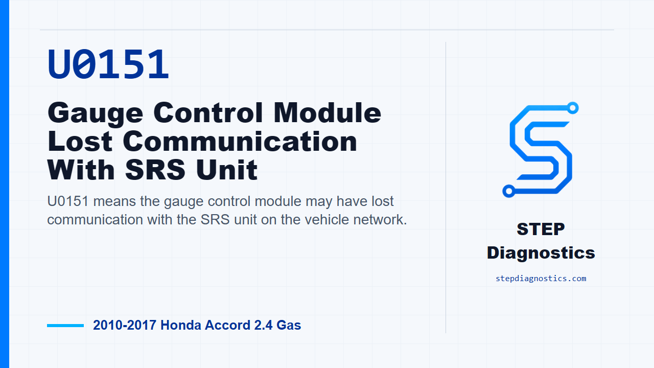
U0151 means the gauge control module may have lost communication with the SRS unit on the vehicle network.
What the vehicle may do
- The vehicle may show warning indicators or communication-related scan data concerns.
- The code can be intermittent if a connector or circuit contact is poor.
- Some vehicles may appear to operate normally while the code is stored.
Possible fault areas
- Possible F-CAN communication wiring concern between the gauge control module and SRS unit.
- Possible loose or poor connector contact.
- Possible module-side communication concern after the wiring path checks OK.
Diagnostic path
Opening context
On this 2010 through 2017 Honda Accord with the 2.4 gas engine, U0151 means the gauge control module may have lost communication with the SRS unit. In plain terms, the cluster side and the airbag control side are not talking the way the network expects. Depending on the vehicle, you may see warning indicators, communication-related scan data issues, or the code may simply come back during a scan. The broad fault areas can include a possible communication wiring issue, a poor connector fit, or a module-side problem. We are going to keep this one focused on the diagnostic path for U0151.
Before testing and code verification
Before you start, save the freeze data and any on-board snapshot information, then look over the basic troubleshooting information. Now clear the DTCs with the HDS. Turn the ignition switch to LOCK (0) and then back to ON (II), or use the engine start/stop button to select OFF mode and then ON mode. Wait for at least 6 seconds, then check for DTCs again with the HDS.
Decision after verification
If U0151 does not reset, treat it as an intermittent failure. The system is OK at this time, so concentrate on loose or poor connections. If U0151 is indicated again, move into the F-CAN line check between the gauge control module and the SRS unit.
F-CAN open-wire check
With the ignition in LOCK (0), or the vehicle in OFF mode, disconnect gauge control module connector A, the 32P connector, and SRS unit connector A, the 39P connector. Check continuity through each F-CAN leg. For F-CAN_H, check between gauge control module connector A (32P) No. 19, WHT, and SRS unit connector A (39P) No. 34, WHT with the asterisk noted for that SRS circuit. For F-CAN_L, check between gauge control module connector A (32P) No. 20, RED, and SRS unit connector A (39P) No. 35, RED with the asterisk noted for that SRS circuit. Keep in mind, wire colors may be substituted for SRS circuits, so identify the circuit by connector and terminal, not color alone.
Interpreting the wire check
If both F-CAN wires have continuity, the F-CAN wiring between those points checks OK, and the diagnostic call is to replace the gauge control module. If continuity is missing, the result points to an open or poor connection in the F-CAN wiring between the SRS unit and the gauge control module. Do not jump past that result; stay with the wiring fault indicated by the test path before making a module decision.
Closing takeaway
The clean way through U0151 is simple: save the captured data, clear and recheck the code, then only if it returns, prove the F-CAN_H and F-CAN_L paths between the gauge control module and the SRS unit. If the circuit is open, stay on the circuit or connection issue. If the circuit has continuity, follow the module result from the diagnostic path. For more diagnostic training, visit stepdiagnostics.com.
Final check
For this code, first confirm whether U0151 resets, then test the communication wiring before making a module decision.
For more guided automotive diagnostics, visit STEP Diagnostics.