What this code means
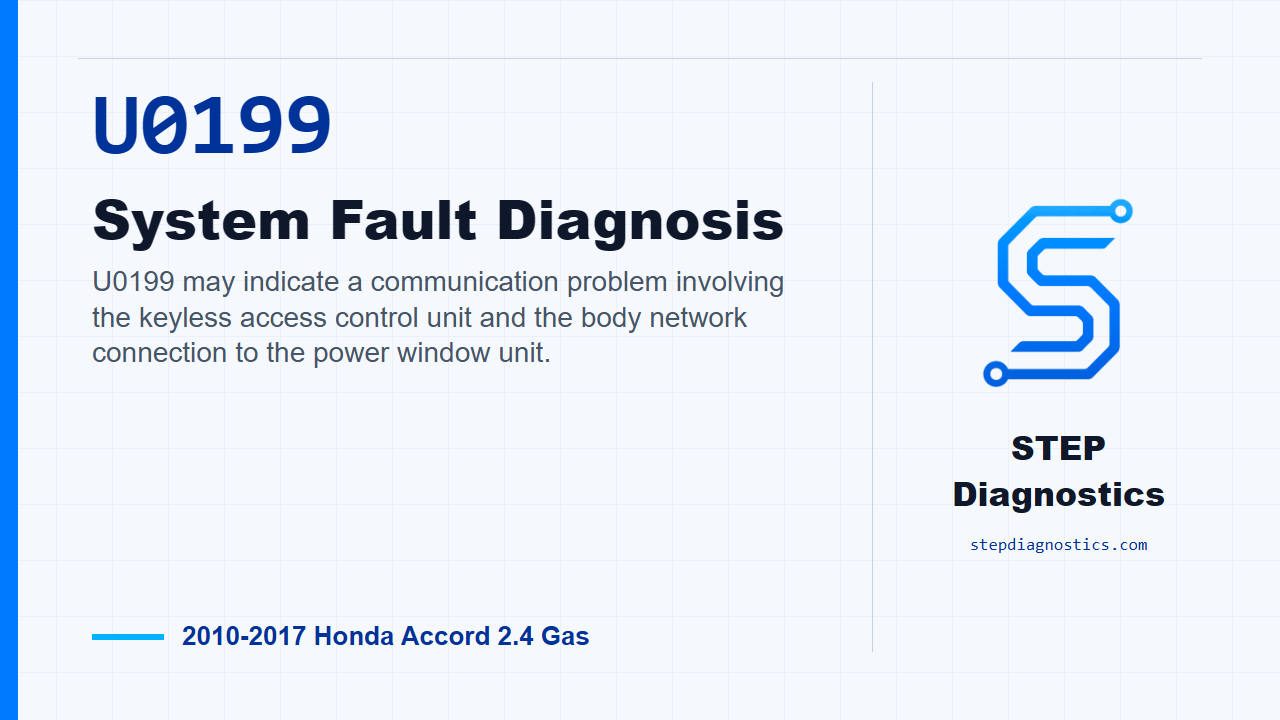
U0199 may indicate a communication problem involving the keyless access control unit and the body network connection to the power window unit.
What the vehicle may do
- The vehicle may have keyless access or body electrical symptoms.
- Power window related functions may be affected in some cases.
- The code can also be intermittent if a connector or wiring issue only appears under certain conditions.
Possible fault areas
- Possible power feed or fuse circuit problem.
- Possible ground circuit problem.
- Possible loose, poor, or high-resistance connector condition.
- Possible B-CAN wiring issue between the keyless access control unit and the power window master switch.
Diagnostic path
Open and code meaning
On this Accord, U0199 is a body network communication code tied into the keyless access control unit. In plain terms, the keyless access control unit may not be seeing the power window unit on the B-CAN network the way it expects. Depending on the fault, the vehicle may have keyless access complaints, body electrical issues, or window-related symptoms, but the diagnostic path here is electrical: first prove the code is current, then separate a power or ground problem from a B-CAN line problem.
Confirm whether U0199 is active
Start by clearing the DTCs with the HDS. Press the engine start/stop button to OFF, then back to ON. Wait for at least 6 seconds, then check for DTCs again. If U0199 comes right back, continue with the communication and circuit checks. If it does not come back, treat it as an intermittent at this point. The system is OK right now, so inspect for loose terminals, poor connector fit, or a connection that only drops out under certain conditions.
Use the B-CAN unit information to choose the path
Next, use the HDS body electrical menu and check the connected control units information. Look at the DETECT or NOT AVAILABLE status for the power window unit. If the power window unit shows DETECT, skip ahead to the B-CAN line check between the keyless access control unit and the power window master switch. If it does not show DETECT, stay on the power and ground side first, because the power window master switch may not be powered up or grounded well enough to communicate.
Check the fuses before circuit voltage testing
If the power window unit is not detected, check fuse No. A21, rated at 10 A, in the under-hood fuse/relay box, and fuse No. B1, rated at 7.5 A, in the under-dash fuse/relay box. If both fuses are OK, move on to voltage testing at the power window master switch connector. If either fuse is not OK, replace the fuse. If it blows again, repair the short to ground in the No. A21 and/or No. B1 fuse circuit.
Check the +B BACK UP feed
With the engine start/stop button in OFF mode, disconnect the power window master switch 37P connector. Check voltage on the +B BACK UP circuit between connector terminal No. 26, the white wire, and body ground. You are looking for battery voltage. If battery voltage is present, that feed is OK and you can move to the IG2 feed. If battery voltage is not present, repair the open or high resistance in that wire.
Check the IG2 feed
Now press the engine start/stop button to ON mode, with the power window master switch 37P connector still disconnected. Check voltage on the IG2 circuit between connector terminal No. 25, the light green wire, and body ground. Again, the expected result is battery voltage. If battery voltage is present, the IG2 wire is OK and the next check is ground continuity. If battery voltage is not present, repair the open or high resistance in that wire.
Check the ground circuits
Return the engine start/stop button to OFF mode. With the power window master switch 37P connector still disconnected, check ground continuity individually from terminal No. 3, the black wire, to body ground, and from terminal No. 31, also a black wire, to body ground. If both have continuity, the ground circuits are OK and the next step is the B-CAN wiring. If continuity is missing, repair the open or high resistance in the ground wire or the poor ground at G501.
Check the B-CAN line between the units
For the B-CAN check, keep the power window master switch 37P connector disconnected, and disconnect keyless access control unit connector B, the 28P connector. In OFF mode, check continuity on the B CAN-H circuit between power window master switch connector terminal No. 28, the pink wire, and keyless access control unit connector B terminal No. 6, also the pink wire. If there is no continuity, the fault is an open or poor connection in the B CAN-H wire between the keyless access control unit and the power window master switch. If there is continuity, the diagnostic path points toward an open or poor connection in the B CAN-L side between those same units. If the B-CAN path is not clear and appears to repeat the same B CAN-H points, pause, recheck the earlier diagnostic path, and avoid guessing at a B CAN-L pinout.
Verify after the repair
After repairing the indicated fuse circuit, power feed, ground, or B-CAN wiring issue, verify it the same way you started. Clear the DTCs with the HDS, cycle OFF and then ON, wait for at least 6 seconds, and check for U0199 again. The goal is simple: the code should stay gone under the same conditions that originally brought it back.
Takeaway
The clean way through U0199 is to prove whether the code is current, see whether the power window unit is detected on the body network, then test power, ground, and the B-CAN wiring in order. Do not jump to modules until the basic circuits have been proven. For more diagnostic training, visit stepdiagnostics.com.
Final check
This code is often approached by confirming whether it is current, then separating power and ground faults from network wiring faults.
For more guided automotive diagnostics, visit STEP Diagnostics.