What this code means
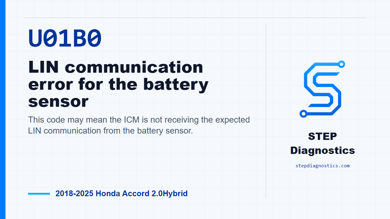
This code may mean the ICM is not receiving the expected LIN communication from the battery sensor.
What the vehicle may do
- The vehicle may show charging or electrical power-management symptoms.
- Stop-start or energy-management behavior may be affected.
- The vehicle may also store the code with few obvious driver symptoms.
Possible fault areas
- Possible loose or poor connection at the battery sensor near the battery negative terminal.
- Possible issue in the LIN battery sensor circuit.
- Possible issue in the battery sensor power feed circuit.
- Possible shorted component connected to the LIN battery sensor circuit.
- Possible ICM involvement after the related inspections are normal.
Diagnostic path
Opening context
On this Accord Hybrid, U01B0 is a LIN communication fault involving the battery sensor signal and the ICM. In plain terms, the ICM may not be receiving the battery sensor signal it expects over the LIN line. The vehicle may show charging, stop-start, or electrical-management symptoms, or it may simply store the code. The possible fault areas are the battery sensor connection, the LIN circuit, the power feed for that circuit, another component tied into the same LIN path, or the ICM after the rest of the checks come back normal. Before diving into circuit testing, start with the basic troubleshooting approach so the simple checks do not get skipped, and check for loose terminals at the battery sensor on the battery negative terminal.
Confirm the fault condition
To confirm the code path, turn the vehicle to the ON mode and wait 60 seconds. Treat that as the monitor gate for this fault. You want the car in the operating state where the ICM can decide whether it is receiving the battery sensor signal correctly.
Check the battery sensor signal behavior
Next, move to the battery sensor inspection. Disconnect the battery sensor connector. With that connector disconnected, check the unit output voltage inspection using the female terminals with IG Mode ON. The expected result is that there is any voltage. There is no direct standalone test for the battery sensor itself in this diagnostic path, so the decision is made by checking the related circuits and components around it. If this inspection is normal, the path points to a problem with the battery sensor. If it is abnormal, keep going because the problem is in another related area.
Inspect the LIN and power circuits
Now isolate the +B_STOP and LIN battery sensor circuits. Disconnect the battery sensor connector, disconnect the shutter grille connector if the vehicle is equipped with a shutter grille, and disconnect ICM connector P. With IG Mode OFF, check the LIN battery sensor open wire inspection. The normal result is less than 1 Ω. Then check the +B_STOP circuit. The normal result is 12 V battery voltage. After that, check the LIN battery sensor circuit for a short to ground with IG Mode OFF. The normal result is more than 1 MΩ. If this circuit inspection is abnormal, the fault is in the circuit. If the power supply check is abnormal, continue with the power supply inspection to locate the failure instead of condemning a module.
Isolate anything connected to the LIN circuit
If the external circuit is normal, inspect the components connected to the LIN battery sensor circuit. Start with the battery sensor connector disconnected, the shutter grille connector disconnected if equipped, and ICM connector P disconnected. Then reconnect the shutter grille connector, if equipped, and ICM connector P one at a time while performing the inspection. This test can be done earlier because it covers the connected items, but if it fails, do not stop there. Go back through the individual inspection items so you know which item actually failed. With the battery sensor connector still disconnected, using the female terminals and IG Mode OFF, the connected-part internal circuit inspection should show not shorted. If the inspection turns abnormal when a part is reconnected, the problem is with the part that shorted when it was brought back onto the LIN circuit.
ICM decision point
Only after the other inspection items indicate a normal condition does this path leave the ICM as the remaining cause. In other words, do not jump to the ICM early. Let the sensor check, the LIN open check, the +B_STOP feed check, the short-to-ground check, and the connected-component isolation lead you there.
Verification and takeaway
For verification, keep it separate from the testing. After the fault area is corrected, put the vehicle back into the same confirmation condition, turn the vehicle to the ON mode, wait 60 seconds, and confirm the code stays gone. The key takeaway is to treat U01B0 as a LIN communication diagnosis: verify the sensor connection first, prove the LIN and +B_STOP circuits, isolate anything else on that LIN leg, and only leave the ICM for last. For more diagnostic training, visit stepdiagnostics.com.
Final check
Diagnose the communication path in order: connection, sensor output behavior, LIN and power circuits, connected components, then the ICM only after the earlier checks are normal.
For more guided automotive diagnostics, visit STEP Diagnostics.