What this code means
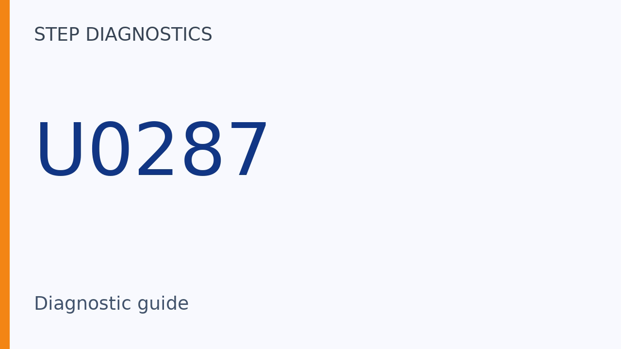
U0287 can indicate that electric oil pump speed stays too low after the TCM commands it to start.
What the vehicle may do
- Pump speed may stay low after a TCM start command.
Possible fault areas
- Possible fault areas include the electric oil pump and its relay.
- The external circuits and TCM can also be involved.
Diagnostic path
Understanding U0287
On this 2025 Honda Accord 1.5, U0287 means Lost Communication With Electric Oil Pump. The TCM can store this code when the pump motor speed stays below a specified speed for a certain period after a start command. The checks cover the pump, its relay, the external circuits, and the TCM. Here is what this code tells us. Pump speed may stay low after a TCM start command. Here are the main areas to check. Possible fault areas include the electric oil pump and its relay. The external circuits and TCM can also be involved.
Before troubleshooting
Before you troubleshoot, review How to Troubleshoot.
Check the listed prerequisite first
Troubleshoot any DTCs listed or indicated systems below first. DC-DC Converter \[PGM-FI\]: DTC P0A94
What the checks cover
The dotted line marks the components to be tested. The illustration does not show every area that needs checking. The checks call for the Electric Oil Pump Relay Test and the Electric Oil Pump Test. The external circuit checks cover EOPSIG, EOPSTS, and EOPGND, followed by +B_EOP \[DCDC_OUT2\]. They also cover EOPRLY \[EOP_RLY_CL-\] and EOPVB \[EOP_RLY_OUT\]. The remaining item is the TCM Inspection.
Confirmation procedure
Here is the separately defined confirmation procedure. Turn the vehicle to ON mode. Use the diagnostic scanner (HDS) function Electrical Oil Pump Activation. Drive the electric oil pump for at least 5 seconds.
EOPSIG wire check
The listed scanner functions are AT > Function Test > Electrical Oil Pump Activation and AT > Data List. This is the separate EOPSIG, EOPSTS, EOPGND circuit inspection. Before you disconnect the TCM connector, jump the SCS line with the scanner. Wait more than 1 minute before disconnecting it. This inspection requires both the TCM connector (50P) and electric oil pump connector (4P) to be disconnected. For the EOPSIG open-wire check, keep IG Mode OFF and both connectors disconnected. Place one probe on TCM connector (50P) female terminal 40. Place the other probe on electric oil pump connector (4P) female terminal 3. The normal reading is less than 1 ohm. An abnormal reading means there is a problem in the circuit.
EOPSTS wire check
Keep IG Mode OFF, with the TCM connector (50P) and electric oil pump connector (4P) disconnected. To check EOPSTS, place one probe on TCM connector (50P) female terminal 50. Place the other probe on electric oil pump connector (4P) female terminal 2. The normal reading is less than 1 ohm. An abnormal reading means there is a problem in the circuit.
EOPGND wire check
Keep IG Mode OFF and both connectors disconnected for the EOPGND check. Place one probe on electric oil pump connector (4P) female terminal 1. Place the other probe on body ground. The normal reading is less than 1 ohm. An abnormal reading means there is a problem in the circuit.
EOPSIG ground-short check
For the following short-circuit checks, use the Open/Shorted Wire Inspection Description method as circumstances require. For EOPSIG, keep IG Mode OFF, with the TCM connector (50P) and electric oil pump connector (4P) disconnected. Place one probe on electric oil pump connector (4P) female terminal 3. Place the other probe on body ground. The normal reading is more than 1 megohm. An abnormal reading means there is a problem in the circuit.
EOPSTS ground-short check
For the EOPSTS short-to-ground check, keep IG Mode OFF and both connectors disconnected. Place one probe on electric oil pump connector (4P) female terminal 2. Place the other probe on body ground. The normal reading is more than 1 megohm. An abnormal reading means there is a problem in the circuit.
The open-wire and ground-short checks answer different questions. EOPSIG and EOPSTS need continuity along their specified wire paths, but no continuity to body ground. Passing an open-wire check therefore does not also pass the ground-short check. EOPGND is different: its specified path to body ground needs continuity. With IG Mode OFF and both connectors disconnected, less than 1 Ω means continuity, while more than 1 MΩ means no continuity. An abnormal result identifies a problem in the circuit being checked.
+B_EOP terminal 4 check
This is the separate +B_EOP \[DCDC_OUT2\] open-wire inspection. It requires the electric oil pump relay and DC-DC converter connector B (5P) to be disconnected. With IG Mode OFF, place one probe on electric oil pump relay socket (4P) female terminal 4. Place the other probe on DC-DC converter connector B (5P) female terminal 5. The normal reading is less than 1 ohm. An abnormal reading means there is a problem in the circuit.
+B_EOP terminal 12 check
Keep IG Mode OFF, with the electric oil pump relay and DC-DC converter connector B (5P) disconnected. Check the second +B_EOP \[DCDC_OUT2\] path. Place one probe on electric oil pump relay socket (4P) female terminal 12. Place the other probe on DC-DC converter connector B (5P) female terminal 5. The normal reading is less than 1 ohm. An abnormal reading means there is a problem in the circuit.
These two +B_EOP measurements share DC-DC converter connector B (5P) female terminal 5, but use different relay socket terminals: 4 and 12. A normal result on one path does not establish the result on the other. Each has its own less-than-1 Ω requirement with IG Mode OFF, the relay disconnected, and connector B disconnected; an abnormal result points to a circuit problem.
EOPRLY wire check
This is the separate EOPRLY \[EOP_RLY_CL-\] open-wire inspection. It requires the TCM connector (50P) and electric oil pump relay to be disconnected. Before you disconnect the TCM connector, jump the SCS line with the scanner. Wait more than 1 minute before disconnecting it. For the measurement, keep IG Mode OFF. Place one probe on disconnected TCM connector (50P) female terminal 27. Place the other probe on electric oil pump relay socket (4P) female terminal 11. The normal reading is less than 1 ohm. An abnormal reading means there is a problem in the circuit.
EOPVB wire check
This is the separate EOPVB \[EOP_RLY_OUT\] open-wire inspection. It requires the electric oil pump connector (4P) and relay to be disconnected. With IG Mode OFF, place one probe on electric oil pump connector (4P) female terminal 4. Place the other probe on electric oil pump relay socket (4P) female terminal 3. The normal reading is less than 1 ohm. An abnormal reading means there is a problem in the circuit.
When the checks point to the TCM
For the TCM Inspection, the conclusion depends on all the other inspection items. If every other item checks out normally, the remaining TCM is determined to be the cause.
This is a conclusion reached by excluding the other listed inspection items, not by passing the wire checks alone. The Electric Oil Pump Relay Test and Electric Oil Pump Test are also part of that condition. A normal result from only some of these inspections does not satisfy the stated condition for identifying the TCM as the cause.
Wire-check conditions
For the wire checks, follow each troubleshooting check's specific inspection points and measurement conditions. For an open-wire check, the normal condition is less than 1 Ω, meaning continuity. For a shorted-wire check, the normal condition is more than 1 MΩ, meaning no continuity. For a short-to-power voltage check, the normal reading is 0 V.
Electric Oil Pump Relay Test
Here is the separate Electric Oil Pump Relay Test named earlier. The relay must be removed for this test. The required tool is Relay Puller 07AAC-000A2A1. Use the relay chart to identify the type and its matching test. The electric oil pump relay uses the Normally-open four-terminals type test. Check the relay using that test table and Figures 1 and 2. The table calls for a continuity check at terminals 1 and 2. For its voltage check, battery power positive connects to terminal 3 and negative connects to terminal 4. If the result is not as specified, replace the power relay.
Prepare for the pump pressure test
Here is the separate Electric Oil Pump Test named earlier. Check for DTCs. If any DTCs are stored, troubleshoot and clear them first. Keep all foreign particles out of the transmission. Transmission fluid may run out of the inspection port when installing or removing the A/T oil pressure gauge. Be sure to check the transmission fluid level after the test. Pressure is measured at the driven pulley pressure inspection port. Select pressure gauge adapters A and E. Other pressure gauge adapters are not used. The required tools are Pressure Gauge Adapter 070AJ-RT4A101, A/T Low Pressure Gauge w/Panel 07406-0070301, A/T Pressure Test Hose 07AAJ-PY4A100, and A/T Pressure Adapter 07MAJ-PY40120. Before assembly, the scanner must be connected. The CVT driven pulley pressure sensor must be removed. The transmission fluid level must be normal. Install the pressure sensor with its sealing washer to pressure gauge adapter A. Assemble the gauge by installing the A/T Low Pressure Gauge w/Panel, A/T Pressure Test Hose, and A/T Pressure Adapter to pressure gauge adapter A. Install pressure gauge adapter E to the driven pulley pressure inspection port. Install pressure gauge adapter A to pressure gauge adapter E. Connect connector (c) to the CVT driven pulley pressure sensor (d). Temporarily install the air cleaner housing assembly.
Measure driven pulley pressure
Start the engine. Warm it up by raising engine speed around 3,000 rpm until the cooling fan or fans come on. Turn the engine off. On the scanner, select AT (System Selection Menu), then Function Test, then Electrical Oil Pump Activation. Do not drive the electric oil pump for more than 160 seconds at a time. Measure the driven pulley pressure while driving the electric oil pump. Look for 216 - 270 kPa (2.20 - 2.75 kgf/cm2, 31.3 - 39.2 psi). That is the standard pressure range.
The confirmation procedure and pressure test use Electrical Oil Pump Activation for different purposes. The confirmation procedure specifies activation for at least 5 seconds in ON mode. The pressure test evaluates the driven pulley pressure while the pump is driven, after the stated warm-up and with the engine off. Completing activation alone does not establish that pressure is within the standard range. The 160-second limit is a maximum per activation, not a required measurement duration.
Remove the test equipment
Keep foreign particles out of the transmission during removal. Transmission fluid may run out when you remove the A/T oil pressure gauge. Remove the air cleaner housing assembly. Disconnect the connector from the pressure sensor. Remove pressure gauge adapters A and E. Remove the pressure sensor and sealing washer from pressure gauge adapter A. Install the pressure sensor with a new sealing washer. Install the air cleaner housing assembly. If the pressure test result is abnormal, replace the electric oil pump. After the test, check the transmission fluid level.
Final check
The TCM can be identified as the cause only when the other inspection items indicate normal conditions.
For more guided automotive diagnostics, visit STEP Diagnostics.