What this code means
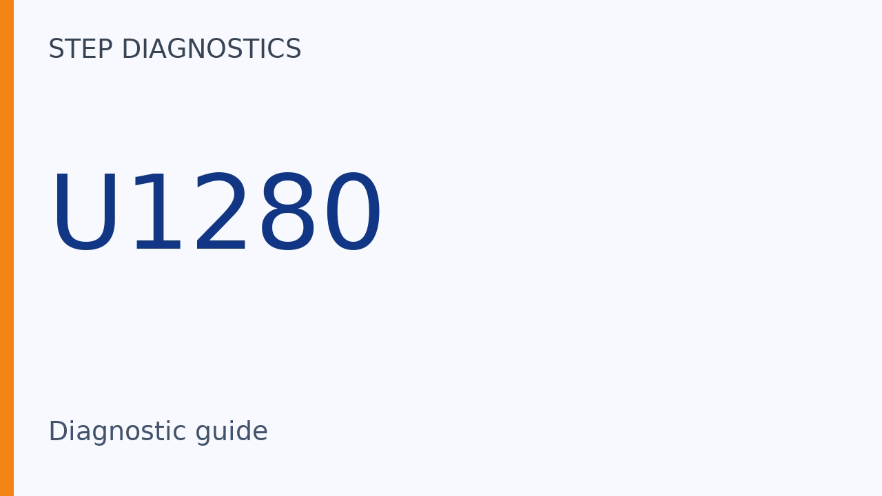
U1280 can indicate that the automatic lighting control unit-sensor has detected BUS-OFF status in the B-CAN circuit.
What the vehicle may do
- U1280 can be stored when B-CAN BUS-OFF status is detected.
Possible fault areas
- Possible fault areas include the B-CAN circuit and control-unit communication.
Diagnostic path
What U1280 means
On this 2025 Honda Accord 1.5, U1280 means B-CAN communication bus line error (BUS-OFF). The automatic lighting control unit-sensor stores this code when it detects BUS-OFF status in the B-CAN circuit. We will call that component the lighting sensor. These checks focus on B-CAN communication and which control units are communicating. Here is what this code tells us. U1280 can be stored when B-CAN BUS-OFF status is detected. Here are the main areas to check. Possible fault areas include the B-CAN circuit and control-unit communication.
Before troubleshooting
Before you troubleshoot, review How to Troubleshoot.
Check the concurrent-code prerequisite
Troubleshoot the following DTCs first, if stored at the same time. - Network Communications \[CAN Gateway\]: DTC U1280-00
If Network Communications \[CAN Gateway\]: DTC U1280-00 is stored at the same time, troubleshoot it first.
When multiple codes are present
If you are troubleshooting multiple DTCs, follow B-CAN System Diagnosis Test Mode A.
Test Mode A: initial checks
B-CAN System Diagnosis Test Mode A is the separate procedure for initial communication and DTC checks. Here is how that procedure begins. Check the PCM for DTCs. Troubleshoot PCM or F-CAN loss of communication errors first. Then continue with this diagnosis if the symptom is related to the B-CAN system.
Check whether the symptom relates to B-CAN
Compare the symptom with these B-CAN related systems. They include the Gauge control module, Exterior lights, Turn signals, Entry light control, Interior lights, and Safety indicators. They also include Horns (security and panic), Reminder chimes (seat belt, lights-on, and parking brake), and the Power window/moonroof timer. Continue the comparison with Wiper/Washer, Security, Keyless entry, Power door locks, Dashlights brightness, Immobilizer, and Daytime running lights. Also included are Keyless access control, Climate control, Seat heater, Audio and visual system, and Telematics system. Finally, compare Driving support, BSI system, Wireless charger, and Driving Position Memory System (DPMS). If the symptom is related to B-CAN, continue with the scanner connection and communication check. If it is not related to B-CAN, use the symptom troubleshooting for the affected system.
This comparison sets the scope of the diagnosis; it does not identify a failed control unit. A symptom related to the listed B-CAN systems leads to the communication check, while an unrelated symptom leads to troubleshooting for the affected system.
Check control-unit communication
Connect the diagnostic scanner (HDS) to the DLC. From BODY ELECTRICAL SYSTEM SELECT, select B-CAN CONTROL UNITS INFORMATION. Then select CHECK CONNECTED CONTROL UNITS. Check whether these control units are communicating with the scanner: Body control module, Gauge control module, Climate control unit, and Automatic lighting control unit-sensor. Also check Power window master switch, Relay control module, Front seat heater control unit, and Telematics control unit. Continue with Left side BSI radar unit, Right side BSI radar unit, Left front lighting control unit, and Right front lighting control unit. Then check Power seat control unit, Center display unit, and Infotainment control unit. Look for DETECT when a unit is communicating. NOT AVAILABLE means the unit is not communicating or the vehicle is not equipped with it. The scanner checks this status only once when BODY ELECTRICAL is selected. To recheck the status after repair, reboot the scanner. If all control units are communicating, continue to the affected system's DTC check. If any control units are not communicating, go to B-CAN System Diagnosis Test Mode B. If none are communicating, or only the body control module is communicating, go to body control module DTC U1280 troubleshooting.
NOT AVAILABLE alone does not establish a communication fault: the same display also applies when the vehicle is not equipped with that unit. DETECT has a narrower meaning—it confirms that the unit is communicating with the HDS.
The displayed status is a one-time check, not a continuously updated view. After repair, leaving the same screen open does not provide a fresh communication result; rebooting the HDS is the stated way to recheck.
Read the affected system's codes
If all control units are communicating, select the system with the problem from BODY ELECTRICAL SYSTEM SELECT. Then select DTCs. If any DTCs are indicated, continue by recording and sorting those codes.
Communication and DTC results answer different questions. All units communicating allows the procedure to move to the affected system's DTCs; it does not mean that system has no stored codes. If codes are indicated, their types determine the required troubleshooting order.
Use the required code order
Record all DTCs, and sort them by DTC type. Troubleshoot Internal error DTCs first. Next, troubleshoot Loss of communication DTCs. Then troubleshoot Signal error DTCs. Finally, troubleshoot Receiving malfunction information DTCs.
Final check
Control-unit communication status and DTC type can guide the troubleshooting path.
For more guided automotive diagnostics, visit STEP Diagnostics.