What this code means
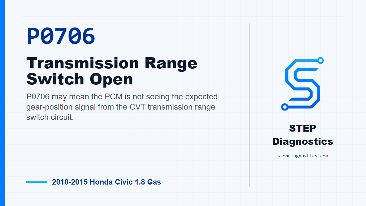
P0706 may mean the PCM is not seeing the expected gear-position signal from the CVT transmission range switch circuit.
What the vehicle may do
- The vehicle may store the code with range-switch or shift-related symptoms.
- The gear position information may be incorrect or missing.
- The complaint may be intermittent if the circuit fault is not present during testing.
Possible fault areas
- Possible range switch signal circuit issue
- Possible PG ground-side issue
- Possible transmission range switch issue
- Possible connector or wiring issue
- Possible shift cable adjustment concern
- Possible PCM software or PCM operation concern after circuit checks pass
Diagnostic path
Opening context
P0706 on this 2010 to 2015 Honda Civic with the 1.8 gas engine points to an open in the CVT transmission range switch circuit. In plain terms, the PCM may not be seeing the correct gear-position signal from the range switch. The vehicle may show range-related symptoms, may have shift or engagement complaints, or may simply store the code. On this diagnostic path, keep it electrical: the possible fault areas are the range switch signal circuits, the PG ground side, the switch itself, connector condition, shift cable adjustment, and, only after the circuit checks pass, PCM software or PCM operation. This code is not diagnosed as a mechanical transmission failure.
Start with verification and cable adjustment
Start with the basic system checks, then verify the problem. Before chasing the circuit, make sure the shift cable is adjusted properly. After that, turn the ignition switch to ON (II), or use the engine start/stop button to select ON mode. With the HDS, compare the transmission range switch signal inputs in each shift lever position against the expected range-switch pattern. If the signals look correct, treat it as an intermittent at this moment and try to reproduce the same conditions that were captured when the code set. If the failure is present, continue with the circuit checks.
Identify whether the switch inputs are all missing
Next, look at the range switch inputs again with the HDS in each shift lever position and decide whether all of the transmission range switch signals are indicating OFF. If they are all OFF, the diagnostic path moves to the PG ground-side check. If they are not all OFF, record which circuit is abnormal, because that specific circuit becomes the line you test next. On vehicles without paddle shifters, include the L-related circuit information when applying the table.
Simulate the suspect switch signal
For a single abnormal range signal, turn the ignition switch to LOCK (0), or select OFF mode. Disconnect the transmission range switch 10P connector. Then connect terminal A to terminal B with a jumper wire. Terminal A is the circuit that did not indicate ON during the earlier HDS check, and terminal B is body ground. Turn the ignition back to ON (II), or select ON mode, and check that same transmission range switch signal with the HDS. If the signal now indicates ON, the wiring side responded to the jumper and the range switch is the failed part. If it still does not indicate ON, the switch itself is not the problem on that path, so continue to the open-wire check for that corresponding line.
Check the corresponding signal wire for an open
Now check the suspect signal line between the range switch connector and the PCM. Turn the ignition switch to LOCK (0), or select OFF mode. Jump the SCS line with the HDS, then disconnect PCM connector B (51P). With the transmission range switch 10P connector disconnected and PCM connector B (51P) disconnected, check continuity between the listed test point for the suspect circuit and body ground, one circuit at a time. If there is continuity, the wire checks OK. At that point, update the PCM if it does not have the latest software, or substitute a known-good PCM, then recheck. If P0706 goes away after an update, the troubleshooting is complete. If it goes away with a substituted PCM, replace the original PCM. If there is no continuity, repair the open between the corresponding transmission range switch connector terminal and the PCM.
If all switch signals are OFF, check the PG ground path
If the earlier HDS check showed all range switch signals OFF, move to the PG line. Turn the ignition switch to LOCK (0), or select OFF mode, and disconnect the transmission range switch 10P connector. Check continuity between transmission range switch 10P connector No. 5 (BLK) and body ground. The test condition is IG LOCK (0) or OFF mode with the transmission range switch 10P connector disconnected. If there is continuity, the PG wire is OK and the range switch is the failed part. If there is no continuity, repair the open in the PG wire between the transmission range switch and body ground G101, or repair the poor body ground at G101.
Verify the repair
Keep the verification separate from the pinpoint tests. After the wiring repair, switch replacement, PCM update, or PCM confirmation path is complete, recheck the system and confirm P0706 does not return. The key takeaway is simple: do not condemn the transmission mechanically for this code. Prove whether the PCM can see the range switch inputs, then isolate the open signal line, PG ground issue, range switch fault, or PCM path in that order. For more diagnostic training, visit stepdiagnostics.com.
Final check
P0706 on this path is handled as an electrical range-switch circuit diagnosis, not a mechanical transmission diagnosis.
For more guided automotive diagnostics, visit STEP Diagnostics.