What this code means
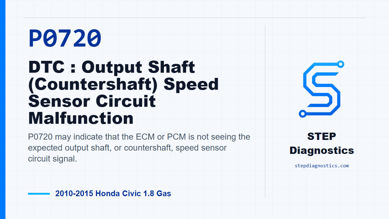
P0720 may indicate that the ECM or PCM is not seeing the expected output shaft, or countershaft, speed sensor circuit signal.
What the vehicle may do
- The vehicle may have speed-signal related drivability concerns.
- Shift behavior may be affected on some vehicles.
- The fault can be intermittent if the signal returns during testing.
Possible fault areas
- A possible sensor circuit issue may be involved.
- Connector condition or loose terminals can be involved.
- Wiring between the sensor and ECM may be involved.
- The ECM or PCM side of the circuit may be involved.
Diagnostic path
Set up the diagnosis
On this 2010 to 2015 Honda Civic with the 1.8 gas engine, P0720 points to the output shaft, or countershaft, speed sensor circuit. In plain language, the ECM or PCM may not be seeing the speed signal it expects from that sensor circuit. The vehicle may have speed-signal related drivability or shift concerns, and the possible fault areas can include the sensor, its connector and wiring, or the ECM side of the circuit. Before testing, save the captured data and any on-board snapshot information, then start with the basic checks so you know whether this is a hard fault or an intermittent connection issue.
Verify the fault first
Start the engine and hold it at 3,000 rpm with no load, in neutral, until the radiator fan comes on. Then let it idle. After that, test-drive the vehicle for several minutes and watch C SHAFT SPD in the HDS data list. If vehicle speed is shown there, treat this as intermittent for now. The system is OK at this moment, so concentrate on poor connections or loose terminals at the output shaft speed sensor and the ECM. If no vehicle speed is indicated, move into circuit testing.
Check the VCC1 feed
With the ignition switch in LOCK (0), disconnect the output shaft speed sensor 3P connector. Turn the ignition switch ON (II), then measure voltage on the VCC1 circuit from terminal No. 3, the YEL/RED wire, to body ground. You are looking for about 5.0 V. If that voltage is present, the VCC1 wire is OK and you continue to the NC circuit check. If it is not present, repair the open in the VCC1 wire between the sensor 3P connector and ECM connector C23, then verify the repair.
Use the NC voltage check to choose the next branch
Next, with the ignition still ON (II) and the sensor connector still disconnected, measure the NC circuit at terminal No. 2, the BLK/WHT wire, to body ground. Again, the question is whether you have about 5.0 V. If you do, go check the SG1 side. If you do not, go after the NC circuit for a short or open.
If the NC voltage is present, check SG1
For the SG1 check, measure between terminal No. 1, the GRN/WHT wire, and terminal No. 3, the YEL/RED wire, at the disconnected output shaft speed sensor connector. The expected result is about 5.0 V. If that reading is present, the SG1 wire is OK, and the next repair is to replace the output shaft speed sensor, then verify the repair. If that reading is not present, repair the open in the SG1 wire between ECM connector C24 and the output shaft speed sensor, then verify the repair.
If the NC voltage is missing, check for a short first
If the NC circuit did not show the expected voltage, turn the ignition switch back to LOCK (0). Jump the SCS line with the HDS, disconnect ECM connector B, the 49P connector, and check continuity from ECM connector B terminal No. 48, the BLK/WHT wire, to body ground. If there is continuity, repair the short in the NC wire between the rocker arm oil pressure switch and the ECM at B48, then verify the repair. If there is no continuity, the NC wire is not shorted, so continue with the open check.
Then check the NC circuit for an open
With the ignition still in LOCK (0), the output shaft speed sensor connector disconnected, and ECM connector B disconnected, check the NC wire between sensor connector terminal No. 2 and ECM connector B terminal No. 48. If continuity is present, the NC wire is OK. At that point, update the ECM if it does not have the latest software, or substitute a known-good ECM, then verify the repair. If continuity is not present, repair the open in the NC wire between ECM B48 and the output shaft speed sensor, then verify the repair.
Verify the repair and confirm the code stays gone
For verification, reconnect all connectors, turn the ignition switch ON (II), reset the ECM with the HDS, and perform the ECM idle learn. Then test-drive under the monitor conditions: ECT SENSOR 1 above 176 °F (80 °C), transmission in 5th, engine speed between 2,000-3,000 rpm, drive for several minutes, then decelerate with the throttle fully closed for 8 seconds. After that, check for Pending or Confirmed DTCs with the HDS. If P0720 is still indicated, recheck for poor connections or loose terminals at the output shaft speed sensor and the ECM. If the ECM was updated, substitute a known-good ECM and recheck. If the ECM was substituted, go back and start the diagnostic path again. If P0720 is not indicated, troubleshooting is complete. If a known-good ECM was substituted, replace the original ECM. If any other pending or confirmed codes are present, handle those separately by their own diagnostic path.
Takeaway
The takeaway: prove the sensor feed, signal, and ground side before condemning anything, and keep verification separate from testing. For more diagnostic training, visit stepdiagnostics.com.
Final check
This diagnosis often comes down to proving the sensor circuit path in order, then verifying that P0720 stays gone under the required operating conditions.
For more guided automotive diagnostics, visit STEP Diagnostics.