What this code means
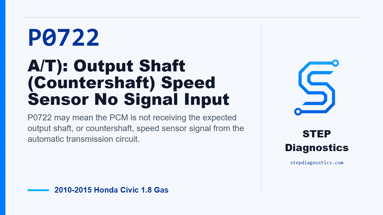
P0722 may mean the PCM is not receiving the expected output shaft, or countershaft, speed sensor signal from the automatic transmission circuit.
What the vehicle may do
- The vehicle may have shift complaints or speed-related transmission behavior.
- The code can sometimes appear with limited obvious drivability symptoms.
Possible fault areas
- Possible fault areas often include the output shaft speed sensor circuit, connector condition, sensor power feed, signal circuit, ground side, or PCM input.
Diagnostic path
Code overview and setup
P0722 on this 2010 to 2015 Honda Civic with the 1.8 gas engine is a no-signal fault for the automatic transmission output shaft, or countershaft, speed sensor circuit. In plain terms, the PCM may not be seeing the shaft speed signal it needs. The vehicle may have shift complaints, speed-related transmission issues, or the code may show up with little obvious drivability change. The possible fault area is mainly electrical: the sensor circuit, connector condition, sensor power, signal, ground side, or the PCM input. For this code, treat it as an electrical circuit problem, not a mechanical transmission failure. Before testing, save the captured data and any on-board snapshot with the HDS, then start with the basic system checks.
Duplicate the fault first
Start by verifying the problem before you tear into the circuit. Turn the ignition switch to ON (II), clear the DTC with the HDS, then safely raise the vehicle so the front wheels can rotate freely. Block the rear wheels if you are lifting the front, or use a lift, and make sure the vehicle is securely supported. Start the engine, turn VSA off with the VSA OFF button, put the shifter in D, and run the vehicle at speeds over 12 mph (20 km/h). Watch the A/T Data List and compare input shaft, mainshaft, speed to output shaft, countershaft, speed. Then slow down and stop the wheels. If the two speeds are about the same, treat it as an intermittent failure and the system is OK at this time. If they are not about the same, the fault is duplicated and you move into circuit testing.
Check the VCC1 feed
With the failure duplicated, check the VCC1 line first. Turn the ignition switch to LOCK (0), disconnect the output shaft, countershaft, speed sensor 3P connector, then turn the ignition switch back to ON (II). Measure voltage from connector No. 3, the YEL/RED wire, to body ground. You are looking for about 5 V. If about 5 V is there, the VCC1 wire is OK and you continue to the next circuit check. If it is not there, repair an open in the VCC1 wire between the speed sensor and the PCM, then go to repair verification.
Use the NC voltage check to choose the next path
Next, leave the ignition ON (II) and the sensor 3P connector disconnected, and check the NC circuit. Measure voltage from connector No. 2, the BLK/WHT wire, to body ground. Again, the question is whether there is about 5 V. If about 5 V is present, go check the SG1 side. If about 5 V is not present, go after the NC wire for a short-to-ground or open condition.
If NC voltage is present, check SG1 continuity
If the NC circuit showed about 5 V, turn the ignition switch to LOCK (0) and check SG1. With the output shaft, countershaft, speed sensor 3P connector still disconnected, check continuity between connector No. 1, the GRN/WHT wire, and body ground. If there is continuity, the SG1 wire is OK; replace the output shaft, countershaft, speed sensor, then verify the repair. If there is no continuity, repair an open in the SG1 wire between the speed sensor and the PCM, then verify the repair.
If NC voltage is missing, check the NC wire
If the NC circuit did not show about 5 V, turn the ignition switch to LOCK (0), jump the SCS line with the HDS, and disconnect PCM connector B, the 49P connector. With the speed sensor 3P connector disconnected and PCM connector B disconnected, check continuity between connector No. 2, the BLK/WHT wire, and body ground. If there is continuity, repair a short to ground in the NC wire between the speed sensor and the PCM. If there is no continuity, the NC wire is not shorted, so repair an open in the NC wire between the speed sensor and the PCM. After either repair, move to verification.
Verify the repair
For verification, reconnect all connectors, turn the ignition switch to ON (II), and clear the DTC with the HDS. Start the engine, turn VSA off, put the shifter in D, and run the vehicle again at speeds over 12 mph (20 km/h). Compare input shaft, mainshaft, speed to output shaft, countershaft, speed in the A/T Data List, then slow down and stop the wheels. If the speeds are about the same, troubleshooting is complete. If the speeds are still not about the same after the circuit path has been handled, replace the PCM.
Takeaway
The key on P0722 is to prove the no-signal complaint first, then stay disciplined: check the 5-volt feed, use the NC voltage result to pick the correct branch, confirm SG1 or NC integrity, and only then verify the repair under the same operating conditions. For more diagnostic training, visit stepdiagnostics.com.
Final check
This diagnosis should be approached as a possible electrical signal or circuit issue, using circuit checks before making conclusions.
For more guided automotive diagnostics, visit STEP Diagnostics.