What this code means
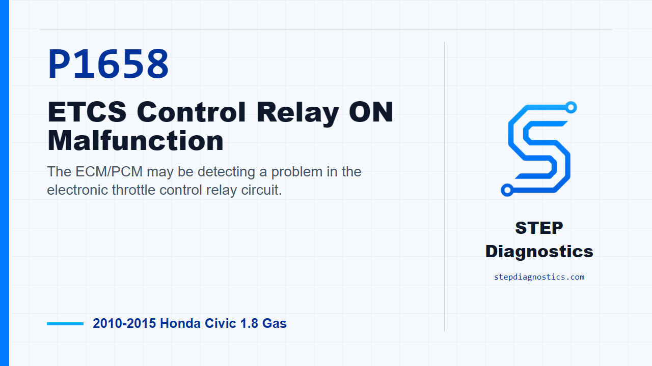
The ECM/PCM may be detecting a problem in the electronic throttle control relay circuit.
What the vehicle may do
- The vehicle may show a warning light.
- Throttle response can be affected.
- Reduced power behavior may occur depending on how the fault is active.
Possible fault areas
- Possible ETCS control relay issue.
- Possible relay or PCM connector concern.
- Possible relay control wiring concern.
- Possible throttle-body power feed wiring concern.
- Possible PCM-side control concern.
Diagnostic path
Opening context and setup
On this 2010-2015 Honda Civic with the L4-1.8L engine, P1658 is an ETCS control relay ON malfunction. In plain language, the ECM/PCM may be seeing a problem in the electronic throttle control relay circuit. The car may show a warning light, and throttle response or reduced-power behavior can show up depending on how active the fault is. Broadly, this can involve the ETCS control relay, the relay control wiring, the throttle-body power feed wiring, connections at the relay or PCM, or the PCM side of the circuit. Before getting deep into pin checks, start with the basic system checks and follow a structured diagnostic approach.
Verify whether the relay circuit fault is present
Start by turning the ignition switch to ON (II), or pressing the engine start/stop button to select ON mode. Then run the ETCS test with the HDS and look at whether the RELAY circuit checks OK. If the RELAY circuit is OK during the test, treat this as an intermittent failure. At that point, the system is OK right now, so inspect for poor connections or loose terminals at the ETCS control relay and at the PCM. If captured operating data is available for this code, try to reproduce the captured conditions instead of guessing. If the RELAY circuit is not OK, the failure is duplicated, and the next move is the relay test.
Test the ETCS control relay
With the fault duplicated, turn the ignition switch to LOCK (0), or press the engine start/stop button to select OFF mode. Remove the ETCS control relay from the under-dash fuse/relay box, then test the relay. If the relay tests OK, keep going into the circuit checks. If the relay does not test OK, replace the ETCS control relay.
Check the relay control side for a short to ground
If the relay itself is OK, leave the ignition in LOCK (0), or OFF mode, and jump the SCS line with the HDS. Disconnect PCM connector A, the 51P connector. With the ETCS control relay disconnected and PCM connector A disconnected, check continuity on the DBW_RLY_CL- circuit between PCM connector A, 51P, terminal No. 50, the yellow wire, and body ground. If there is continuity, repair the short in the DBW_RLY_CL- wire between PCM A50 and the throttle body. If there is no continuity, that relay control line is OK, so move to the VBDBW power-side check.
Check the VBDBW line for a short to power
Next, disconnect PCM connector C, the 51P connector. Turn the ignition switch to ON (II), or press the engine start/stop button to select ON mode. With the ETCS control relay disconnected, PCM connector A disconnected, and PCM connector C disconnected, measure voltage on the VBDBW circuit between PCM connector C, 51P, terminal No. 1, the white and green wire, and body ground. If battery voltage is present, repair the short to power in the VBDBW wire between PCM C1 and the throttle body. If battery voltage is not present, the VBDBW wire is OK. At that point, update the PCM if it does not have the latest software, or substitute a known-good PCM.
Verification and takeaway
After that PCM-side decision, verify the result separately. If P1658 goes away after a PCM update, troubleshooting is complete. If P1658 goes away only after substituting a known-good PCM, replace the original PCM. The takeaway is simple: prove the relay circuit fault first, test the relay, check the control wire for a short to ground, check the VBDBW wire for a short to power, and only then move to PCM software or PCM substitution. For more diagnostic training, visit stepdiagnostics.com.
Final check
P1658 is often best approached by proving whether the relay circuit fault is active, then separating relay, wiring, and PCM-side possibilities in order.
For more guided automotive diagnostics, visit STEP Diagnostics.