What this code means
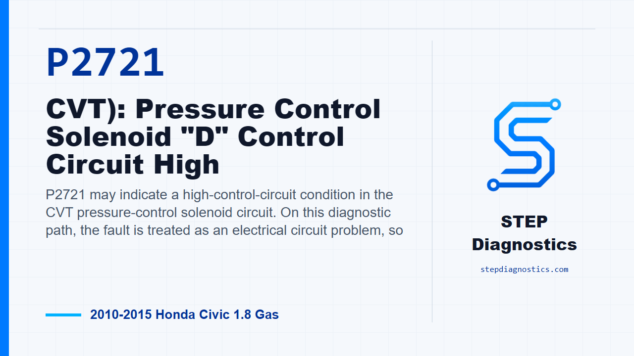
P2721 may indicate a high-control-circuit condition in the CVT pressure-control solenoid circuit. On this diagnostic path, the fault is treated as an electrical circuit problem, so
What the vehicle may do
- The vehicle may turn on a warning light.
- The CVT may change how it controls lockup or pressure operation.
- The vehicle can feel like it is operating in a protective strategy.
Possible fault areas
- Possible wiring or connector faults in the solenoid control circuit.
- Possible solenoid circuit or solenoid wire harness concerns.
- Possible control module side concerns.
Diagnostic path
Opening context
On this 2010 to 2015 Honda Civic with the 1.8 gas engine, P2721 points us toward a high-control-circuit condition in the CVT pressure-control side of the system. In plain terms, the computer may be seeing an electrical problem in the solenoid control circuit rather than a mechanical failure inside the transmission. The vehicle may set a warning light, may change how the CVT applies or controls torque converter lockup, and can feel like it is in a protective strategy. The broad fault areas are possible wiring or connector issues, the solenoid circuit itself, the solenoid wire harness, or the control module side of the circuit. Before getting deep into testing, start with the basic system checks and follow a structured diagnostic approach.
Confirm the fault first
Start the problem verification with the ignition in ON mode. Clear the code with the HDS. Then start the engine and wait for at least 1 second. After that, check for pending or confirmed codes with the HDS. At this point, the path checks for a related circuit code. If that related code is present, treat the failure as duplicated and continue with the component and circuit checks. If it is not present, treat it as an intermittent fault for now. If captured operating data is available, try to reproduce the same conditions instead of guessing.
Decide which branch to follow
Next, test the CVT lock-up clutch control solenoid valve. If the solenoid valve works properly, move to the LCCLS wire short-to-ground check. If the solenoid valve does not work properly, move to the solenoid valve resistance check. That split matters, because one side of the path is looking for the control wire shorted to ground, and the other side is checking the valve and the solenoid wire harness.
Check the LCCLS line for a short to ground
For the LCCLS line check, turn the ignition to LOCK (0), or select OFF mode. Jump the SCS line with the HDS. Disconnect the solenoid wire harness 8P connector on the engine wire harness side, and disconnect PCM connector B, the 51P connector. With the ignition still in LOCK (0) or OFF mode, the solenoid wire harness 8P connector disconnected, and PCM connector B disconnected, check continuity on the LCCLS circuit from solenoid wire harness 8P connector No. 8, the green wire, to body ground. If there is continuity, repair the short to ground in the LCCLS wire between the solenoid wire harness and the PCM. If there is no continuity, the LCCLS wire checks OK. From there, update the PCM if it does not have the latest software, or substitute a known-good PCM, then recheck. If P2721 goes away after the update, that completes that path. If P2721 goes away with a known-good PCM substituted, replace the original PCM.
Check the solenoid valve and solenoid wire harness
If the earlier solenoid functional check did not pass, remove the solenoid wire harness and measure resistance at the CVT lock-up clutch control solenoid valve. The test is done with the ignition in LOCK (0) or OFF mode, the CVT lock-up clutch control solenoid valve 2P connector disconnected, and the solenoid wire harness 8P connector on the valve body side disconnected. Measure between terminal No. 1 and terminal No. 2 at the solenoid valve 2P connector. The expected reading is 4.9-6.6 Ω. If the resistance is 4.9-6.6 Ω, the solenoid valve is OK, so replace the solenoid wire harness. If the resistance is not 4.9-6.6 Ω, the valve is considered faulty, and the repair path is to replace the valve body.
Verify and wrap up
Keep the verification separate from the testing. After the selected repair path, use the same front-end check: clear the code, start the engine, wait for at least 1 second, and check for pending or confirmed codes. The key takeaway on P2721 is to stay electrical: confirm the fault, split the path by solenoid operation, then prove whether the issue is the LCCLS wire, the solenoid wire harness, the valve circuit, or the PCM side. For more diagnostic training, visit stepdiagnostics.com.
Final check
P2721 is often approached by confirming the fault first, then separating wiring, solenoid circuit, harness, and control module possibilities.
For more guided automotive diagnostics, visit STEP Diagnostics.