What this code means
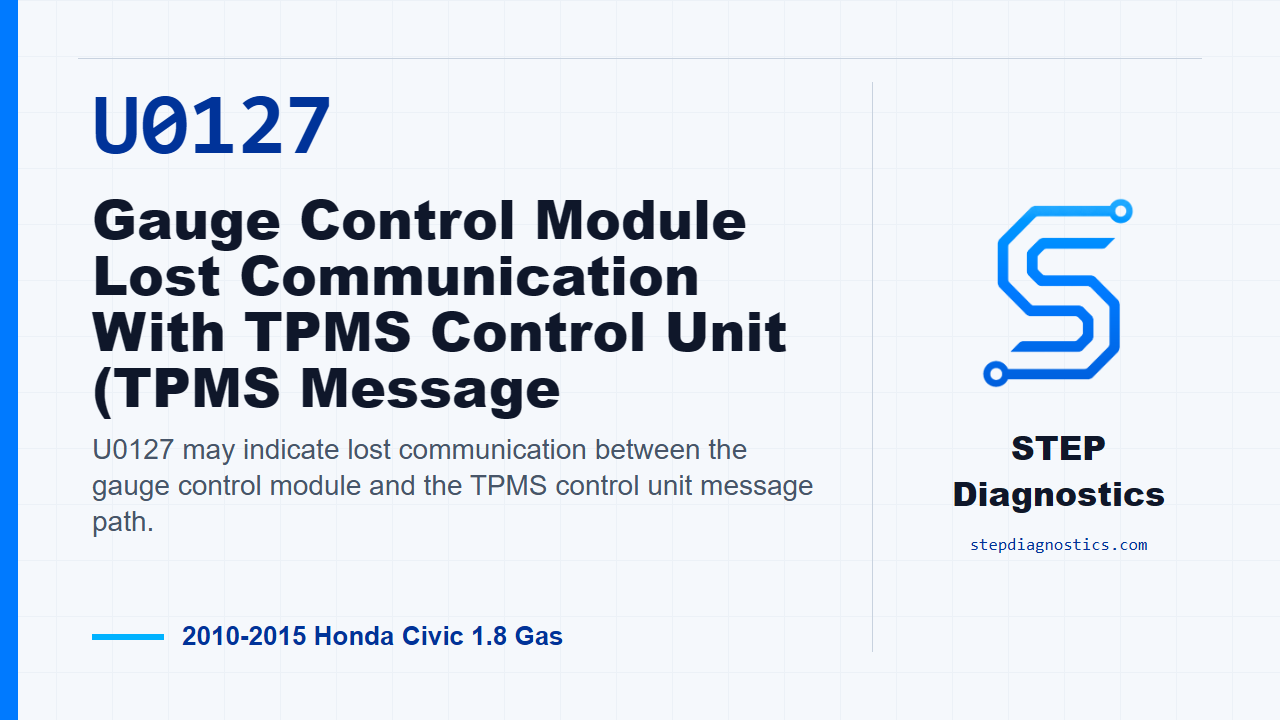
U0127 may indicate lost communication between the gauge control module and the TPMS control unit message path.
What the vehicle may do
- The vehicle may show warning indicators.
- TPMS information may be missing or unreliable.
- The fault may be intermittent if the code does not return after clearing and cycling the ignition.
Possible fault areas
- Possible power feed issue
- Possible ignition feed issue
- Possible ground issue
- Possible loose or poor connector connection
- Possible F-CAN wiring issue between the TPMS control unit and gauge control module
Diagnostic path
Opening context
On this Civic, U0127 is a network communication fault involving the gauge control module and the TPMS control unit. In plain language, the module that displays information may not be receiving the TPMS message it expects. The vehicle may show warning indicators, TPMS information may be missing or unreliable, and the fault can involve power, ignition feed, ground, connector condition, or the F-CAN communication wiring between the modules. Before going deep, if other loss-of-communication codes are present, check what they mean first, and if you’re working with multiple codes, follow a structured diagnostic approach so you don’t chase the wrong network fault.
Verify the problem before testing circuits
Start by clearing the DTCs with the HDS. Turn the ignition switch to LOCK (0), then back to ON (II), wait for at least 6 seconds, and check for DTCs again with the HDS. If the communication fault is not indicated after that reset, treat it as an intermittent failure. At that point, the system is OK right now, so concentrate on loose or poor connections. If the fault is indicated, continue into the power and circuit checks.
Check the TPMS fuse feed first
Next, check fuse No. B40 (7.5 A) in the under-dash fuse and relay box. If that fuse is OK, move on to the TPMS control unit power feed checks. If the fuse is not OK, replace the fuse. If it blows again, repair a short to ground in the No. B40 (7.5 A) fuse circuit before going any farther.
Check the constant power feed
For the +B_TPMS line, turn the ignition switch to LOCK (0), disconnect the TPMS control unit 20P connector, and measure voltage between terminal No. 1, the BLU wire, and body ground. You’re looking for battery voltage on that feed. If battery voltage is present, continue to the ignition feed. If battery voltage is not present, repair an open or high resistance in that wire.
Check the ignition feed
Now check the IG1_METER circuit. With the TPMS control unit 20P connector still disconnected and the ignition switch ON (II), measure voltage between terminal No. 3, the BRN wire, and body ground. If you have battery voltage there, continue to the ground check. If battery voltage is missing, repair an open or high resistance in that wire.
Check the TPMS ground path
For the ground circuit, turn the ignition switch back to LOCK (0). With the TPMS control unit 20P connector disconnected, check the ground path at terminal No. 8, the BLK wire, to body ground. The diagnostic path moves forward on a good result. If the check does not pass, repair an open or high resistance in the ground wire, or a poor ground at G501. If the test method and the expected result do not line up on the car in front of you, pause, recheck the earlier diagnostic path, and avoid guessing.
Check the F-CAN wiring between modules
If the power feeds and ground path check out, move to the F-CAN lines between the TPMS control unit and the gauge control module. With the ignition switch at LOCK (0), disconnect the gauge control module, tach, 32P connector. Check continuity on F_CAN-H between the TPMS control unit 20P connector No. 9, WHT wire, and the gauge control module 32P connector No. 19, WHT wire. Then check F_CAN-L between the TPMS control unit 20P connector No. 20, RED wire, and the gauge control module 32P connector No. 20, RED wire. If continuity is present on the checked lines, the procedure calls for replacing the gauge control module, tach. If continuity is not present, the fault is an open or poor connection in the F-CAN wiring between the TPMS control unit and the gauge control module.
Verification and takeaway
After any repair, verify the repair and confirm the code stays gone under the same basic operating conditions used during the initial check. The main takeaway is simple: prove the fault is current, confirm the TPMS control unit has its fuse power, ignition power, and ground, then prove the F-CAN wiring before condemning a module. For more diagnostic training, visit stepdiagnostics.com.
Final check
Confirm the fault is current, then test fuse power, module power feeds, ground, and F-CAN continuity in order before making a module decision.
For more guided automotive diagnostics, visit STEP Diagnostics.