What this code means
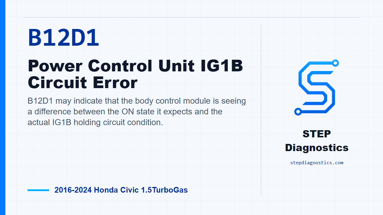
B12D1 may indicate that the body control module is seeing a difference between the ON state it expects and the actual IG1B holding circuit condition.
What the vehicle may do
- The vehicle may have abnormal power mode or ignition-related behavior.
- Keyless access or body-control functions may not behave as expected.
- The code can set when the commanded state and circuit feedback do not agree.
Possible fault areas
- Possible aftermarket accessory interference.
- Possible wiring or connector concerns in the IG1B signal or coil-side circuits.
- Possible under-dash fuse and relay box involvement.
Diagnostic path
Opening context
On this 2016 through 2024 Honda Civic with the 1.5 turbo engine, B12D1 is an IG1B circuit error in the keyless access power control and body control side of the vehicle. In plain language, the body control module may be seeing a mismatch between the ON state it expects and what the IG1B holding circuit is actually doing. The vehicle may have power mode or ignition-related behavior that does not act normally, and the broad fault areas can include aftermarket accessory interference, wiring or connector issues in the IG1B signal and coil circuits, or a possible under-dash fuse and relay box issue.
Start clean
Before getting deep into the circuit checks, start with the basic system checks and follow a structured diagnostic approach. Also make sure aftermarket accessories are not installed, because they can complicate this kind of body-control circuit diagnosis. If you are troubleshooting more than one code at the same time, handle the body network diagnostic path first so you are not chasing a symptom out of order.
Set up the confirmation cycle
Next, reproduce the operating conditions for the fault. Turn the vehicle to the ON mode and wait for at least 10 seconds. Then turn the vehicle to the OFF (LOCK) mode and wait for at least 5 seconds. That cycle is important because this code sets when the body control module compares the ON state it identifies internally against the actual IG1B holding circuit state.
Prepare for circuit inspection
After the confirmation cycle, power the vehicle down and prepare for the circuit checks. Disconnect under-dash fuse and relay box connector D, which is the 16P connector. Then disconnect body control module connector C, which is the 66P connector. From here, the diagnosis is focused on checking the IG1B-related wiring between those points.
Connector identification caution
For these checks, connector cavity identification matters. If the terminal locations are not clear in front of you, pause and verify the connector and cavity information before measuring. Do not guess at terminals on this circuit.
Open-circuit checks
Now perform the listed inspections in order. With IG Mode OFF, check the IG1-B_SIG circuit for an open wire. A normal result is less than 1 Ω. Then, still with IG Mode OFF, check the IG1_COIL+ circuit for an open wire. That circuit is also normal when there is less than 1 Ω.
Short-to-ground check
After the open-wire checks, move to the shorted-circuit inspection. Use the normal open and short inspection method for the circuit being checked, and inspect based on the conditions in front of you. With IG Mode OFF, check IG1-B_SIG for a short to ground. The expected result is not shorted.
Decision logic
The decision point is straightforward. If one of those inspections is abnormal, the problem is in the circuit being tested. If the inspections are normal, the diagnostic path points back to a problem with the under-dash fuse and relay box.
Takeaway and CTA
The takeaway for B12D1 is to prove the body control module’s commanded ON state against the actual IG1B holding circuit, then separate a wiring fault from an under-dash fuse and relay box fault without guessing. For more diagnostic training, visit stepdiagnostics.com.
Final check
Diagnose the IG1B circuit in order: confirm the condition, isolate open or shorted wiring, then use the normal-versus-abnormal result to decide whether the fault stays in the circuit or points back to
For more guided automotive diagnostics, visit STEP Diagnostics.