An EVAP code reports a problem with fuel-vapor control or the pressure response used to check it. It does not, by itself, identify a failed canister, valve, or pressure sensor. The useful starting point is to understand when the system should store vapor, admit air, purge vapor into the engine, or temporarily seal for a check.
This overview covers the 2016-2024 Honda Civic 1.5 Turbo Gas family. Detailed examples use reviewed 2024 Civic Sedan 1.5-liter turbo information for USA/Canada models. The year range does not mean identical equipment, emissions configuration, monitor conditions, or procedures in every year and market. The source also distinguishes Mexico-market operation; do not transfer the USA/Canada valve and monitoring description to another configuration without checking its service information. This is an introduction, not a substitute for the procedure for the vehicle being repaired.
What EVAP does
Fuel in the tank generates vapor. EVAP keeps that vapor from simply escaping to the atmosphere by temporarily storing it in a canister and later drawing it into the engine to be burned. This is vapor management, not the liquid-fuel pressure system that supplies the injectors.
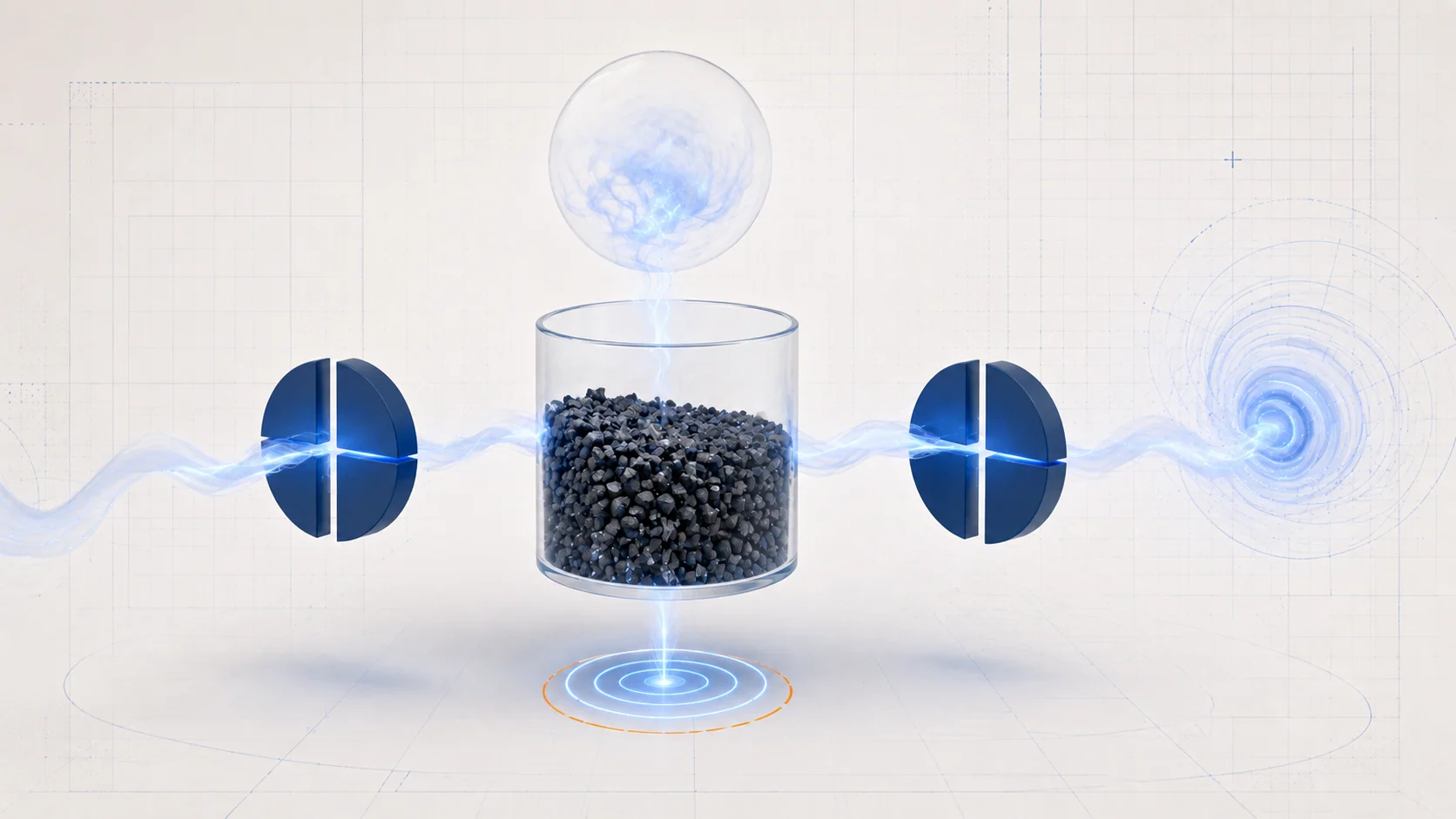
The canister, purge valve, venting path, tank, connecting lines, and pressure feedback work together. Each has a different job:
- Storage: the canister temporarily holds fuel vapor until operating conditions permit purging.
- Purge control: the PCM regulates vapor entering the intake through the canister purge valve. Its duty-cycle command changes the amount of purging rather than merely identifying an always-open or always-closed passage.
- Venting and temporary sealing: in the reviewed USA/Canada arrangement, the canister vent shut valve normally admits outside air through the canister. During an enabled leak check, it closes so that the PCM can evaluate the system's pressure response.
- Pressure feedback: the fuel tank pressure sensor, or FTP sensor, provides the pressure information used by the controller. A reading is meaningful only in the context of the commanded state, actual airflow paths, and test conditions.
These roles explain why a leak, a blocked vent, and an inaccurate pressure signal can lead to different repair paths even though they all belong to EVAP.
Why the turbocharged intake matters
Purge flow needs a suitable pressure difference to draw vapor into the intake. On the reviewed 1.5-liter turbo system, the intake connection used for purging changes with engine conditions and boost pressure. Non-return valves and the purge arrangement support the intended flow path as those conditions change.
That does not make an EVAP fault a turbocharger replacement diagnosis. It means the technician should not assume that one hose or one idle observation represents purge behavior in every operating state. Use the actual configuration's purge-valve and non-return-valve checks when the diagnostic path calls for them. Do not reconstruct the routing from a generic overview illustration or borrow a naturally aspirated engine's test setup.
Pressure response is evidence, not a parts verdict
Tank pressure changes as fuel vapor is generated and as the tank cools. The reviewed leak-code procedure considers pressure behavior after the engine stops. The PCM also uses commanded valve states and pressure feedback during diagnostic testing. These are conditional observations, not continuous proof that the system is healthy or faulty.
Fuel level, fuel condition, temperature, and the required operating state can affect the usefulness of a leak test. Follow the applicable preconditions instead of increasing test pressure or repeating a test under arbitrary conditions. A test that has not run is different from a completed test that passed.
Separate three questions: can the system seal when required, can it vent when required, and does the pressure signal represent the condition being tested? A hose restriction may prevent normal breathing; a sealing defect may prevent the expected pressure response; a sensor or its pressure-reference path may misrepresent that response. None should be assumed from the code title alone.
How the three STEP guides fit together
| STEP guide | What the investigation separates | Avoid this shortcut |
|---|---|---|
| P0455 - EVAP leak detected | Leak confirmation, purge and non-return function, canister-side sealing, venting, fill-side sealing, and the tank. | Assuming a large-leak label identifies one valve or the tank itself. |
| P0456 - EVAP leak detected | The small-leak pressure-response concern and the applicable section-by-section isolation checks. | Deciding that normal drivability means the code can be ignored. |
| P2422 - EVAP venting and pressure diagnosis | Vent restriction or valve behavior versus FTP sensor/reference-path evidence and the canister. | Replacing the vent shut valve simply because its name appears in the fault definition. |
The reviewed direct source groups P0455 and P0456 into a shared procedure, but their leak classifications remain different. P2422 identifies a vent-shut-valve stuck-closed malfunction in the reviewed information. Its shared diagnostic procedure also covers a separate FTP sensor range/performance code, so not every sentence or branch in that document is a stand-alone definition of P2422. Use the actual stored code and the specified initial pressure check to select the applicable path.
Symptoms and useful failure categories
A check engine light may be the only obvious complaint, and the Civic may otherwise drive normally. The absence of a drivability symptom does not establish that vapor containment or the monitor is working correctly. Record what the driver noticed and when it happened without promising that every EVAP failure produces the same symptoms.
Useful categories include damaged or disconnected vapor lines, poor seals or O-rings, a purge or non-return function problem, a restricted vent hose, abnormal vent-valve operation, and FTP sensor or reference-path concerns. The reviewed leak investigation also includes fuel-fill plumbing, vapor recirculation plumbing, the shut-off valve and its sealing surfaces, and finally the tank after the preceding checks.
The fill-side checks are especially important when a technician is tempted to apply a generic fuel-cap diagnosis. In the reviewed configuration, the procedure addresses a main flap unit and shut-off-valve seal. Confirm the actual filler design and follow its instructions; do not assume that tightening or replacing a conventional cap resolves the complaint.
A practical diagnostic approach
- Preserve the evidence. Record pending and confirmed codes, freeze-frame information, available snapshots, the complaint, and relevant recent work before clearing anything. Check related-code priorities and the correct vehicle configuration.
- Establish the intended system state. Confirm the required fuel and operating conditions, then use the prescribed confirmation test. Record whether the monitor failed, passed, or did not complete. Do not interpret those outcomes as equivalent.
- For leak codes, isolate rather than guess. The reviewed procedure includes vent-hose inspection, purge-valve and non-return checks, canister-side visual and sealing checks, vent-valve testing, and fill-side checks. Use each result to narrow the affected section. A failed section test does not automatically identify every part within that section as defective.
- For P2422, distinguish restriction from measurement. The applicable path may include the canister vent hose, vent shut valve, FTP sensor vent hose, sensor port, and canister. Evaluate the initial pressure reading using the specified setup; an unexpected value is not enough to condemn the sensor without separating its reference path and the rest of the system.
- Make the final component conclusion conditional. A canister or tank conclusion at the end of a diagnostic path depends on the earlier required checks being normal. Skipping those checks removes the evidence supporting that conclusion.
This order is a way to organize the work, not a replacement for branch-specific instructions. Exact pressure limits, valve commands, isolation points, connector details, and pass/fail criteria must come from the applicable service procedure.
Repair safely and verify the original concern
Repairs may restore a damaged line or connection, correct a seal, remove a demonstrated restriction using the approved repair method, or replace a proven valve, sensor, canister, fill-side component, or tank. Preserve the intended routing and sealing arrangement. Replacing a named component without demonstrating its failure can leave the original problem untouched.
Fuel vapor is flammable. Keep ignition sources away, provide appropriate ventilation, and follow the specified preparation and isolation steps before disturbing fuel-system connections. Use equipment suitable for the prescribed EVAP test. Never apply unrestricted shop air or extra pressure or vacuum to force a result: the reviewed procedures explicitly warn that exceeding the allowed conditions can damage EVAP parts or the tank. Do not improvise filler opening, hose plugging, or valve actuation from this overview. Running-engine checks also require exhaust ventilation and care around hot and moving parts.
After restoring all disturbed connections, perform the checks and any clearing or learning operations required for the actual repair. Repeat the relevant confirmation test under its enabling conditions, distinguish a completed pass from an incomplete monitor, and check for returning or additional codes. The goal is to show that the same vapor-control or pressure-response concern has been resolved, not simply to extinguish the warning light.