What this code means
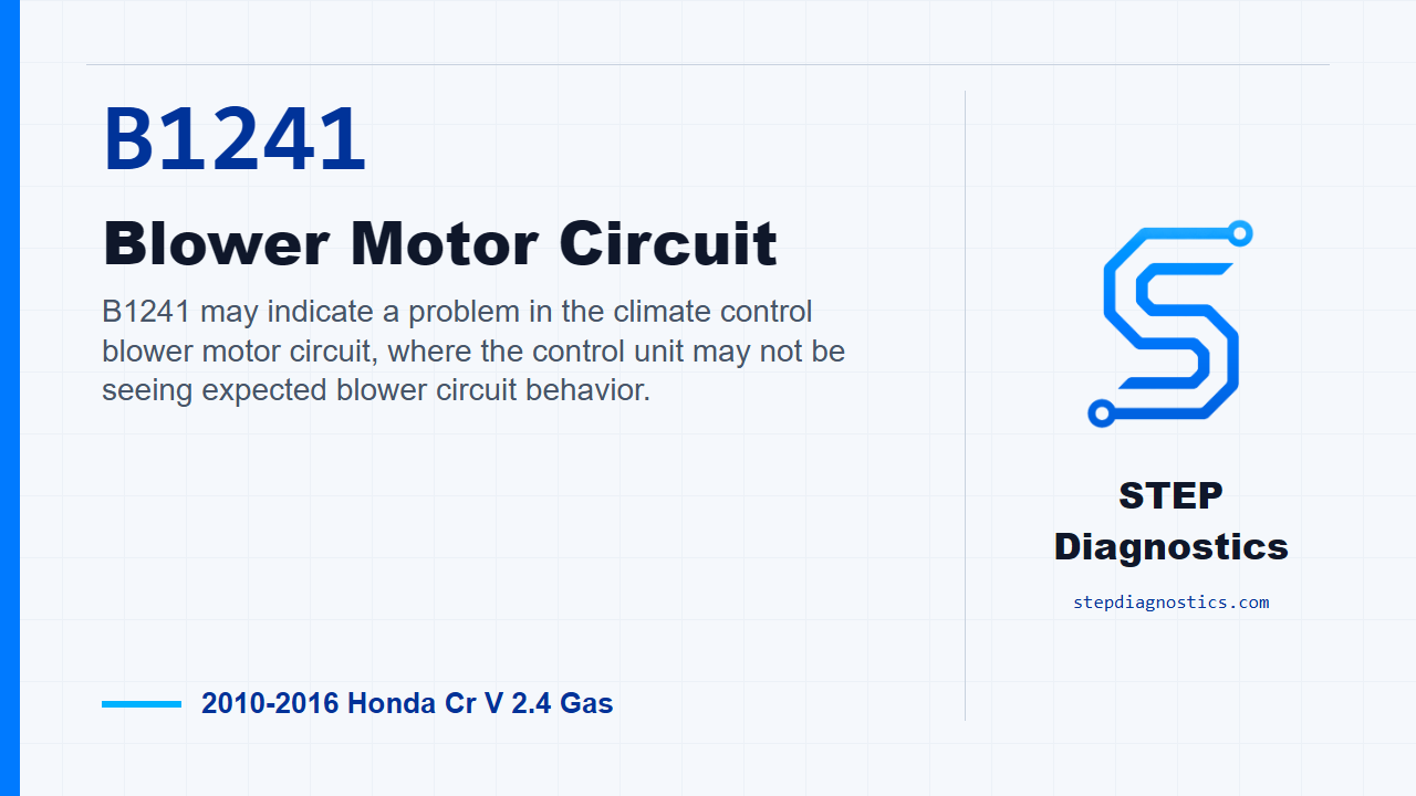
B1241 may indicate a problem in the climate control blower motor circuit, where the control unit may not be seeing expected blower circuit behavior.
What the vehicle may do
- The blower may not run.
- The blower may run only under certain conditions.
- Blower speed control may be poor or inconsistent.
Possible fault areas
- Possible power supply or fuse circuit issue.
- Possible ground issue.
- Possible wiring issue between the climate control unit, power transistor, relay, and blower motor.
- Possible blower motor, relay, power transistor, or climate control unit involvement.
Diagnostic path
Opening context
On this 2010 to 2016 Honda CR-V with the 2.4 gas engine, B1241 points us toward the climate control blower motor circuit. In plain terms, the control unit may not be seeing the blower circuit behave the way it expects. The customer may have a blower that does not run, only runs under certain conditions, or has poor speed control. The broad fault areas can include power supply, ground, wiring between the climate control unit and the power transistor, the blower motor, the relay, or the control side of the circuit. We are going to work it in order and let each test decide the next move.
Confirm the code first
Start by clearing the DTC with the HDS. Turn the vehicle to OFF, LOCK mode, then back to ON mode. Run the self-diagnostic function with the HDS or through the climate control unit, then check for codes again. If B1241, or the matching indicator fault, comes right back, continue into the circuit checks. If it does not come back, treat it as an intermittent failure and inspect for loose wires or poor connections in the blower motor circuit before going any deeper.
Check the main blower fuse and motor feed
With the vehicle OFF, LOCK mode, check fuse No. A2-8, rated at 40 A, in the under-hood fuse and relay box. If the fuse is good, move to the blower motor power feed. If the fuse is blown, replace the fuse and recheck. If it blows again, repair the short in the No. A2-8 40 A fuse circuit. Next, disconnect the blower motor 2P connector, turn the vehicle ON, and measure voltage between blower motor 2P connector No. 2 and body ground. Battery voltage here means the feed side is present, so continue to the blower motor operation check. If battery voltage is not present, skip ahead to the blower motor relay side of the diagnosis.
Force the blower motor on
Turn the vehicle OFF, LOCK mode, reconnect the blower motor 2P connector, then jumper blower motor 2P connector No. 1 to body ground. Turn the vehicle ON. If the blower motor runs at high speed, the motor can run and the path continues toward the ground and control side of the circuit. If it does not run at high speed with that jumper in place, replace the blower motor.
Check the power transistor ground and motor control leg
Turn the vehicle OFF, LOCK mode, remove the jumper wire, and disconnect the power transistor 4P connector. Check continuity between power transistor 4P connector No. 3 and body ground. If there is continuity, the ground wire is okay and you can move on. If there is no continuity, check for an open between the power transistor and body ground. If that wire checks okay, look for a poor ground at G402. Now connect power transistor 4P connector No. 3 to power transistor 4P connector No. 4 with a jumper wire, then turn the vehicle ON. If the blower motor runs at high speed, the BLW-M wire is okay and the diagnosis moves to the signal wires between the climate control unit and the power transistor. If the blower does not run at high speed, repair the open in the wire between the power transistor and the blower motor.
Check the control wires for shorts to ground
Turn the vehicle OFF, LOCK mode, remove the jumper, and disconnect the climate control unit 32P connector. With both the climate control unit 32P connector and the power transistor 4P connector disconnected, check continuity between climate control unit 32P connector No. 8 and body ground. If there is continuity, repair the short to ground in the wire between the climate control unit and the power transistor. If there is no continuity, that BLOWER V, or BLW-V, wire is not shorted. Then check continuity between climate control unit 32P connector No. 7 and body ground. If there is continuity, repair the short to ground in the wire between the climate control unit and the power transistor. If there is no continuity, that BLOWER G, or BLW-G, wire is not shorted, and you can move to open-circuit checks.
Check the control wires for opens
With the vehicle still OFF, LOCK mode, and both connectors still disconnected, check continuity between climate control unit 32P connector No. 8 and power transistor 4P connector No. 2. If there is continuity, the BLOWER V, or BLW-V, wire is okay. If there is no continuity, repair the open in the wire between the climate control unit and the power transistor. Next, check continuity between climate control unit 32P connector No. 7 and power transistor 4P connector No. 1. If there is continuity, the BLOWER G, or BLW-G, wire is okay and the path goes to the power transistor itself. If there is no continuity, repair the open in the wire between the climate control unit and the power transistor.
Test the power transistor
At this point, test the power transistor. Use the correct component test and do not guess at the result. If the power transistor is not okay, replace the power transistor. If the power transistor tests okay, replace the climate control unit. One important note: if the power transistor is faulty, check the blower motor for damage. If necessary, replace the blower motor.
If blower motor feed voltage was missing, check the relay path
If the earlier blower motor feed test did not show battery voltage, turn the vehicle OFF, LOCK mode, remove the blower motor relay from the under-hood fuse and relay box, and test the relay. Use the correct relay test and make the next decision from that result. If the relay is not okay, replace the blower motor relay. If the relay is okay, continue into the relay socket checks.
Check relay socket power and ignition feed
With the vehicle OFF, LOCK mode, the blower motor 2P connector disconnected, and the blower motor relay disconnected, measure voltage between blower motor relay 5P socket No. 1 and body ground. If battery voltage is present, the +B HTR MTR wire is okay. If battery voltage is not present, the path calls that an open in the +B HTR MTR wire, and the repair is to replace the under-hood fuse and relay box. Then turn the vehicle ON and measure voltage between blower motor relay 5P socket No. 3 and body ground. If battery voltage is present, the IG2 A/C wire is okay. If battery voltage is not present, repair the open in the wire between the No. B22 7.5 A fuse in the under-dash fuse and relay box and the blower motor relay.
Check relay ground side and output path
Turn the vehicle OFF, LOCK mode. With the blower motor 2P connector disconnected and the blower motor relay disconnected, check continuity between blower motor relay 5P socket No. 5 and body ground. If there is continuity, repair the open in the wire between the blower motor relay and the blower motor. If there is no continuity, check for an open in the wire between the blower motor relay and body ground. If that wire is okay, check for a poor ground at G402.
Verify the repair
Keep verification separate from the circuit testing. After the repair, clear the DTC, turn the vehicle OFF, LOCK mode, then back ON, run the self-diagnostic function again, and confirm B1241 stays gone. The takeaway is simple: prove power, prove ground, prove the blower can run, then isolate the control wiring, power transistor, relay path, or control unit based on the test result. For more diagnostic training, visit stepdiagnostics.com.
Final check
This code is often best handled by proving the blower power and ground paths first, then isolating the control wiring and command components based on the test results.
For more guided automotive diagnostics, visit STEP Diagnostics.