What this code means
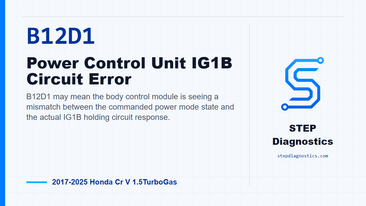
B12D1 may mean the body control module is seeing a mismatch between the commanded power mode state and the actual IG1B holding circuit response.
What the vehicle may do
- The vehicle may have keyless access or power mode complaints.
- A body electrical warning may be present.
- The code may store with few obvious driver symptoms.
Possible fault areas
- Possible IG1B signal or coil circuit concern.
- Possible connector or wiring issue.
- Possible aftermarket accessory influence.
- Possible body control module side concern.
- Possible remaining IG1B relay circuit concern.
Diagnostic path
Opening context
This one is B12D1 on a Honda CR-V, an IG1B circuit error in the keyless access power control unit/body control module area. In plain terms, the body control module may be seeing a mismatch between the power mode it believes it commanded and what the IG1B holding circuit is actually doing. The vehicle may have keyless access or power mode complaints, may set a body electrical warning, or may simply store the code. Broadly, possible fault areas can include the IG1B signal or coil circuits, connector issues, aftermarket accessory interference, the body control module side of the circuit, or the remaining IG1B relay circuit. If other codes are present, check what they mean first and keep this diagnosis focused on B12D1.
Confirm the code under the operating conditions
Start by reproducing the operating conditions for the monitor. Turn the vehicle to ON mode and wait for at least 10 seconds. Then turn the vehicle to OFF (LOCK) mode and wait for at least 5 seconds. The logic behind this code is command versus response: if the body control module identifies an ON state, but the actual IG1B holding circuit does not agree, it stores B12D1.
Prepare for IG1-B signal and coil circuit checks
Before getting into the circuit checks, make sure aftermarket accessories are not installed or influencing the circuit. Then prepare the IG1-B signal and IG1 coil positive inspection. Disconnect under-dash fuse/relay box connector D, the 16-pin connector. After that, disconnect body control module connector C, the 66-pin connector. At this point, both sides needed for the circuit inspection are separated for testing.
Check the IG1-B signal and IG1 coil positive circuits
Now perform the IG1-B_SIG and IG1_COIL+ circuit inspection in order. Use the correct connector and terminal identification before probing. If the terminal detail is not available, pause and do not guess at pin locations. With IG Mode OFF, check the IG1-B_SIG circuit for an open. Normal is less than 1 Ω. Then, still with IG Mode OFF, check the IG1_COIL+ circuit for an open. Normal there is also less than 1 Ω. Next, inspect for the shorted circuit condition as appropriate. With IG Mode OFF, check IG1-B_SIG shorted to ground. Normal is more than 1 MΩ. If any of these circuit checks are abnormal, treat it as a circuit problem in that inspection path.
Use a known-good body control module only for the directed check
If the circuit inspection path does not identify the fault, move to the body control module check. There is no direct test method for this inspection item, so the directed check uses a known-good body control module and then attempts to reproduce the failure. If the failure is reproduced with the known-good unit installed, the problem is with other related components. If the symptom or DTC goes away, the body control module is the faulty item. Do not jump to that conclusion before the circuit checks are handled.
Consider the remaining IG1B relay circuit
If the other inspection items have all indicated normal, the remaining path is the IG1B relay circuit. In that case, the diagnostic conclusion is a problem with the IG1B relay circuit.
Wrap-up and verification mindset
Keep the order tight on this one: reproduce the power mode conditions, isolate the IG1-B signal and coil circuits, use the known-good module check only where directed, and only then call the remaining IG1B relay circuit. The takeaway is simple: B12D1 is a command-versus-actual IG1B circuit problem, so prove the circuit before blaming a module or relay path. For more diagnostic training, visit stepdiagnostics.com.
Final check
B12D1 is best approached as a command-versus-response ignition holding circuit diagnosis: prove the circuits first, then follow the directed module and relay-circuit checks.
For more guided automotive diagnostics, visit STEP Diagnostics.