What this code means
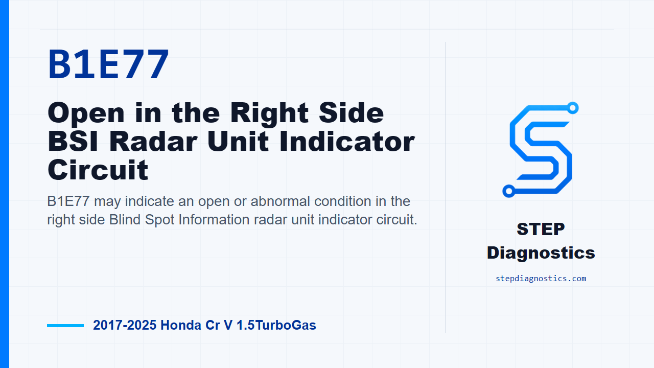
B1E77 may indicate an open or abnormal condition in the right side Blind Spot Information radar unit indicator circuit.
What the vehicle may do
- The blind spot information system may show a warning message.
- The right side alert indicator may not operate normally.
- The system may store a body electrical fault related to the right side blind spot indicator path.
Possible fault areas
- Possible right side BSI alert indicator concern.
- Possible wiring or connector concern in the indicator circuit.
- Possible ground side continuity concern.
- Possible right side BSI radar unit concern after related checks are normal.
Diagnostic path
Open and diagnostic focus
On this Honda CR-V, B1E77 points to a possible open in the right side Blind Spot Information radar unit indicator circuit. The driver may notice a blind spot warning message, or the right side alert indicator may not respond normally. The broad fault areas can include the right side alert indicator, the indicator circuit wiring or connectors, ground side continuity, or the right side BSI radar unit itself. The code sets when the radar unit sees the indicator circuit voltage outside the normal range while that indicator is being commanded on or off. Before getting into the pinpoint checks, start with the basic system checks and follow a structured diagnostic approach so you are not chasing a symptom caused by a larger system issue.
Confirmation
First, confirm the fault under the correct operating state. Turn the vehicle to the ON mode, then wait for at least 5 seconds. That gives the system time to run the check before you move into component and circuit testing.
Right alert indicator bypass check
Next, check the right BSI alert indicator path. There is no direct component-only test for this indicator, so the diagnosis works through the related components and circuit response. Turn the vehicle off as needed, disconnect the right BSI alert indicator connector, and jumper terminals No. 1 and No. 2 at that 2P connector. Then turn the vehicle back to the ON mode. A normal response is that B1E77 changes into the related indicator circuit code. If that normal response happens, the problem is with the right BSI alert indicator. If it does not respond that way, keep going because the fault is in another related part of the circuit.
Open-wire checks
If the indicator bypass check does not isolate the indicator, move to the open-wire inspections. Disconnect the right BSI alert indicator connector and the right side BSI radar unit connector. With IG Mode OFF, check the BSI_R_IND circuit for an open according to the connector terminal information. Normal is less than 1 Ω. Then check the GND circuit the same way, also with IG Mode OFF. Normal is less than 1 Ω. If either check is not normal, the problem is in that circuit. Make sure terminal identification is clear before probing; if the connector terminal locations are not certain, pause, recheck the earlier diagnostic path, and do not guess at terminal placement.
Radar unit conclusion
If the other inspection items all show normal conditions, then the remaining cause is the right side BSI radar unit. The key is the order: confirm the code, use the indicator jumper check, prove the indicator and ground circuits have continuity, and only then make the radar unit call.
Takeaway and close
For B1E77, do not jump straight to the radar unit. Prove the right alert indicator response first, then prove the BSI_R_IND and GND circuits are normal. Once those checks are clean, the radar unit becomes the remaining fault area. For more diagnostic training, visit stepdiagnostics.com.
Final check
B1E77 is best approached as an electrical circuit diagnosis: confirm the fault, test the indicator response, check circuit continuity, then evaluate the radar unit only after the earlier checks are正常.
For more guided automotive diagnostics, visit STEP Diagnostics.