Applicability basis: Authorized vehicle records confirm Honda CR-V 4WD applications with the 1.5-liter turbocharged gasoline engine at the 2017 and 2025 endpoints. Detailed system and diagnostic evidence for this overview was verified against the 2025 L15BE application. Exact component locations, circuit details, scan-tool functions, thresholds, relearn conditions, and service procedures can vary by model year and calibration; use current service information for the vehicle being repaired.
What the electronic throttle control system does
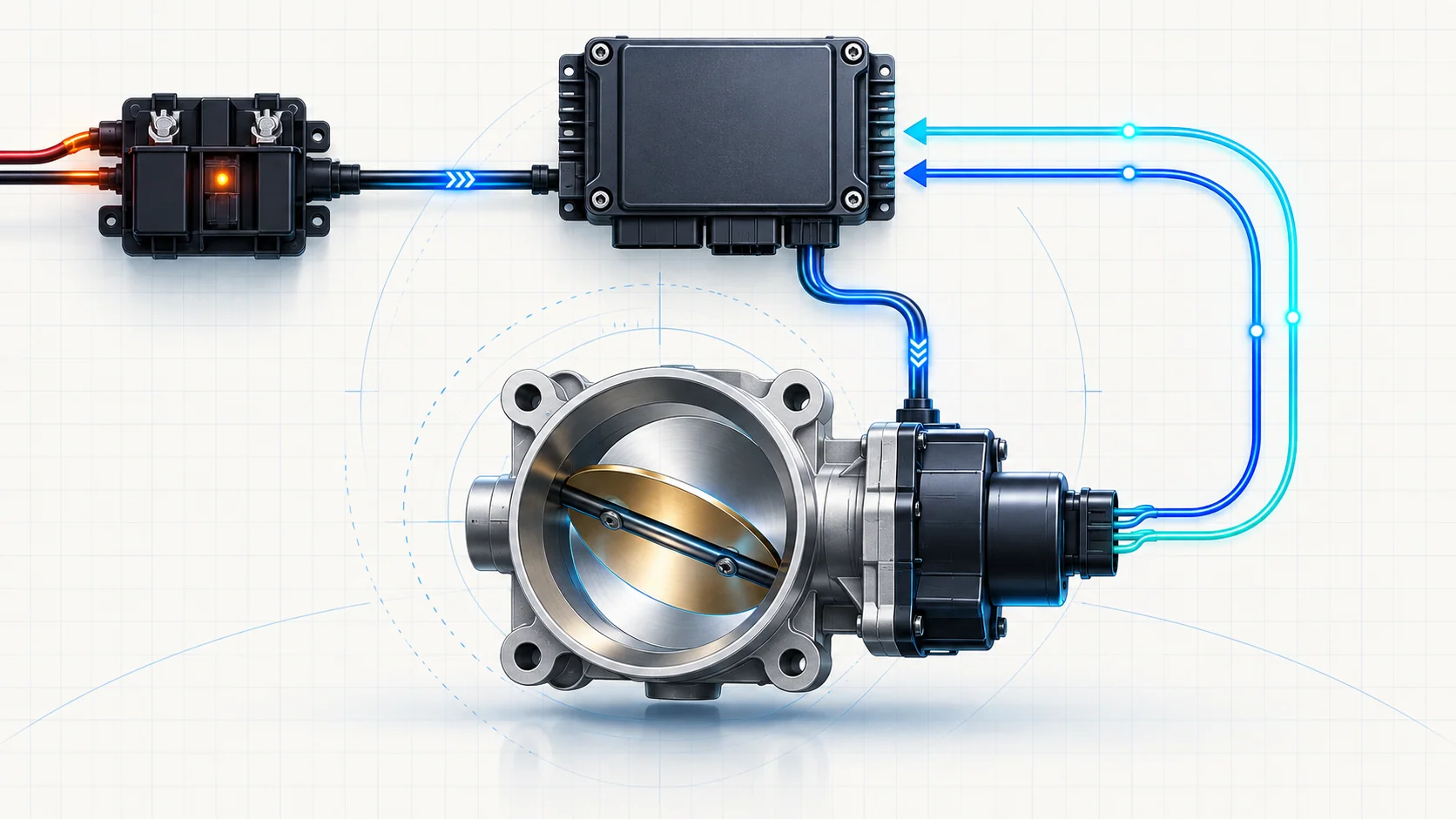
The electronic throttle control system (ETCS) changes engine airflow without a mechanical cable running directly from the accelerator pedal to the throttle plate. The powertrain control module (PCM) interprets the driver's request and current operating conditions, commands an electric motor in the throttle body, and watches position feedback to confirm that the plate moved where expected.
Throttle position affects acceleration and idle airflow. The PCM calculates a target for the current operating condition and checks whether actual movement agrees with that target. An ETCS fault can therefore produce a warning light, limited throttle response, reduced-power behavior, an idle complaint, or little obvious symptom beyond a stored DTC.
A throttle-related DTC identifies a monitored behavior that did not meet expectation. It does not, by itself, prove that the throttle body, relay, wiring, or PCM has failed.
The main functional sections
- Driver request and operating conditions: The PCM uses driver demand and current operating conditions to decide how much throttle opening is appropriate.
- PCM control strategy: The PCM calculates a target throttle position, controls the ETCS power path and throttle motor, compares independent feedback signals, and applies a protective strategy when confidence is lost.
- PGM-FI subrelay and ETCS power feed: The relay-controlled supply must be present when commanded on and absent when commanded off. The PCM monitors whether actual power state agrees with the command.
- Throttle motor and motor circuits: Motor drive moves the plate in either direction. Open, shorted, high-resistance, or poorly connected circuits can prevent commanded movement.
- Throttle plate, shaft, and return spring: The assembly must move freely and return toward its designed default position when motor control is removed. Deposits, binding, wear, or internal damage can change that behavior.
- Redundant throttle-position feedback: Two related signals let the PCM judge plate position and cross-check agreement. Correlation is a plausibility test, not two unrelated readings.
- Learned closed position: The PCM must establish a credible fully closed reference. A contaminated, sticking, electrically faulty, disturbed, or incorrectly serviced throttle system may prevent learning from completing.
How normal ETCS operation fits together
1. The PCM calculates a target
The accelerator pedal represents driver demand. The PCM interprets that request with current operating conditions and calculates a target throttle position. The diagnostic question is whether the commanded power path, motor movement, and position feedback agree with that target.
2. The power path energizes only when expected
The PGM-FI subrelay and associated circuits provide controlled power to the throttle system and related loads. The PCM checks both sides of the logic: power must not remain where it should be off, and required power must not disappear while the relay is commanded on. A relay-state DTC begins as a power and circuit diagnosis, not an automatic throttle-body diagnosis.
3. The motor moves the plate
The PCM drives the motor circuits to open or close the throttle plate. It expects the plate to respond within the strategy's allowed range. A command with no credible movement can originate in the power feed, motor circuits, connector, mechanical throttle assembly, or control module.
4. Feedback proves actual position
Position sensors integrated with the throttle body report actual movement. The PCM compares their signals with each other and with commanded position. Disagreement or failure to reach target directs diagnosis toward signal circuits, motor control, the throttle body, or the PCM in the order specified by current service information.
5. The closed position is learned
The system needs a reliable reference for the closed plate. When learning does not finish or the learned position falls outside the accepted range, the PCM can store an idle-position-learn DTC. The cause may be electrical, mechanical, contamination-related, or a consequence of another throttle fault that should be diagnosed first.
What the related DTCs are telling you
| DTC | Diagnostic category | What it directs you to prove |
|---|---|---|
| P1658 | ETCS relay power present when the monitored state expects it off | Whether the subrelay, control/output circuits, connected loads, or PCM explain the unexpected power state |
| P1659 | ETCS relay power missing when the monitored state expects it on | Whether the power feed, subrelay, open or shorted circuit, connector, or PCM prevents the expected supply |
| P1683 | Throttle valve default-position or return performance | Whether the plate binds, is contaminated, or the throttle body cannot return to the expected mechanical position |
| P2176 | Fully closed/idle position not learned | Whether another throttle fault, motor circuit, throttle-body condition, or controller-side issue prevents a valid learned position |
These categories overlap but are not interchangeable. P1658 and P1659 concern monitored power-state logic. P1683 focuses on mechanical return behavior. P2176 concerns the learned closed reference and can be secondary to another throttle fault. The complete code set determines the diagnostic order.
What the driver or technician may notice
Possible observations include:
- a malfunction indicator lamp with no obvious complaint during a brief check;
- delayed, limited, or inconsistent throttle response;
- reduced-power or fail-safe operation;
- an idle that is high, low, unstable, or unable to relearn after service;
- a fault that appears only during key-on, shutdown, or a learning event;
- several throttle, relay, airflow, or power-supply DTCs that require priority diagnosis.
Symptoms are not failure proofs. An air leak, low system voltage, network issue, engine mechanical fault, or unrelated input can influence idle and throttle behavior without making the throttle body the root cause.
Common failure categories
The commanded power state is wrong
A failed relay, weak power feed, control-circuit fault, output-circuit short or open, terminal problem, or fault in another load sharing the feed can make monitored voltage disagree with the relay command. Diagnose the power path before replacing the throttle body for a relay-state code.
The motor circuit cannot move the plate
Open or shorted motor circuits, spread or corroded terminals, damaged wiring, or an internal motor fault can prevent movement. A click, a momentary response, or a command displayed on a scan tool does not prove that both motor circuits can carry the required current.
The plate binds or does not return normally
Deposits around the bore, a sticking plate or shaft, spring damage, internal wear, or physical damage can keep the plate from reaching target or returning to default position. Cleaning belongs only where the applicable procedure permits it; forcing or prying the plate can create a new fault.
Position feedback is not credible
The PCM needs correlated position signals. Wiring, terminals, reference or ground problems, internal sensor faults, or a mechanical plate that does not match command can make the signals disagree. A correlation fault does not automatically identify which side failed.
The closed position cannot be learned
Learning may fail because another ETCS fault is active, the plate is contaminated or binding, motor circuits are compromised, or the required service procedure has not produced a valid closed-position reference. Diagnose primary faults first, then perform only the learning procedure specified for the exact vehicle.
The PCM is considered too early
The directed sources place the PCM after external power, circuit, connector, and component checks. A control-module conclusion is appropriate only when the specified upstream evidence is normal and the fault remains reproducible.
A practical system-first diagnostic strategy
1. Confirm applicability and preserve evidence
Verify the VIN, model year, engine, drivetrain, software context, and current service procedure. Record confirmed, pending, and history DTCs plus freeze-frame or on-board snapshot data before clearing anything. Note the operating condition in which the complaint occurred and any relevant recent service history without assuming either is the cause.
2. Classify and prioritize the code set
Separate relay/power faults, motor or position-signal faults, mechanical return faults, and learning faults. Resolve low-voltage, reference, communication, and direct ETCS circuit faults before interpreting an idle-position learn code. Follow the exact related-code priority in service information.
3. Inspect before disturbing the system
Check battery and charging condition, grounds, fuses, relay seating, connectors, harness routing, heat or fluid damage, water entry, loose locks, and recent service disturbance. Inspect the air duct and throttle-body joint for an air leak that could mimic an idle-control complaint.
4. Prove the ETCS power path
For P1658 or P1659, compare commanded state with actual supply and isolate the relay control side, output side, feed, connected loads, and terminals using the applicable diagram. Do not substitute a generic relay test for the complete monitored circuit path.
5. Prove motor and feedback circuit integrity
Use terminal-safe methods and exact connector views. Check motor drive and position-feedback paths as directed, including opens, shorts, resistance, power, ground, and terminal fit. Do not pierce sealed wiring or force oversized probes into terminals.
6. Evaluate mechanical movement safely
Disable and prepare the system exactly as specified before inspecting the bore or plate. Look for deposits, binding, damage, or evidence that the plate cannot return normally. Never put fingers or tools into an installed throttle body while it can be energized.
7. Address learning only after primary faults
When circuits and mechanical condition are supported, perform the exact cleaning, reset, or learning procedure required for the vehicle. A scan-tool command is not a shortcut around a power, circuit, or binding fault. If service information calls for a known-good component test, interpret it only after its stated prerequisites pass.
8. Verify the complete repair
Restore every connector, seal, duct, retainer, and harness route. Complete required learning or initialization, then reproduce the original operating condition. Confirm commanded and actual throttle behavior is credible, idle is stable, no related pending DTC returns, and protective operation is no longer active.
Clearing codes and seeing the lamp stay off during a short idle is not repair verification.
Safety before testing or repair
The throttle plate can move suddenly whenever the system is energized. Keep fingers, tools, rags, and test leads out of the installed throttle body during key-on, scan-tool actuation, cranking, and engine operation. Follow the exact disable procedure before touching the plate or removing the throttle body.
Running tests place the technician near the cooling fan, belts, pulleys, hot turbocharger and exhaust components, and moving linkage. Secure clothing and test leads, allow hot parts to cool, and use ventilation appropriate for engine operation.
Disconnecting control-module or throttle-body connectors can require a defined shutdown and wait sequence. Follow current service information so module state and stored energy are handled correctly. Use approved terminal adapters and do not guess connector orientation.
Match the repair to the proven failure
The supported repair may involve a relay, fuse or power-feed fault, wiring or terminal repair, a shared-load problem, throttle-body cleaning where permitted, throttle-body replacement, connector correction, harness routing, required learning, or—only after upstream checks pass—PCM diagnosis and repair controlled by the exact service information.
Avoid replacing the throttle body for every P1658/P1659, replacing the relay for a mechanically sticking P1683, or performing repeated idle learns for a P2176 while a primary circuit fault remains. The correct repair is the one supported by the complete code set and directed test results.
Final takeaway
The 2017-2025 Honda CR-V 1.5 Turbo Gas electronic throttle control system is a closed-loop airflow actuator: the PCM commands a target, the relay and circuits provide controlled power, the motor moves the plate, redundant sensors report position, and the PCM learns a closed reference.
Diagnose it in layers. Preserve the evidence, classify the DTCs, prove power and circuit integrity, inspect mechanical movement safely, correct primary faults before learning, and verify the repair under the original conditions. The linked STEP guides provide model-specific educational direction; current Honda service information for the exact CR-V controls connector references, values, commands, cleaning, learning, replacement, and final verification.