What this code means
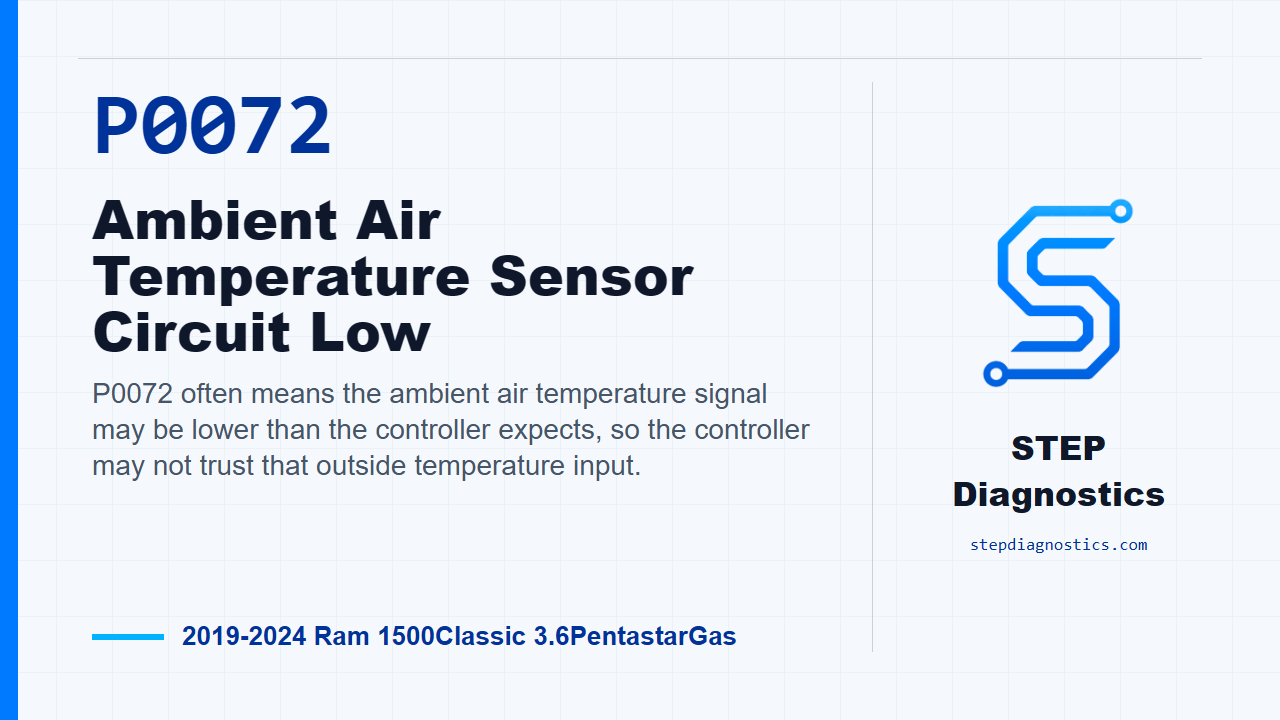
P0072 often means the ambient air temperature signal may be lower than the controller expects, so the controller may not trust that outside temperature input.
What the vehicle may do
- The MIL may illuminate.
- The outside temperature reading may be incorrect or unavailable.
- Systems that use ambient temperature information may react differently when the signal is not trusted.
Possible fault areas
- Possible ambient air temperature sensor connector issue.
- Possible temperature signal circuit short to ground or sensor ground.
- Possible ambient air temperature sensor fault.
- Possible controller or module-side issue after wiring checks are proven good.
Diagnostic path
Opening and fault direction
On this Ram 1500 Classic, P0072 is an ambient air temperature sensor circuit low fault. In plain terms, the controller may be seeing the outside temperature signal pulled lower than expected. The truck may turn the MIL on, and the outside temperature data may be wrong or not trusted by the system. Broadly, this can be a possible connector problem, a signal circuit shorted to ground or to the sensor ground, a possible sensor fault, or less often a controller issue. Start with the basic system checks. If other codes are present, check what they mean first, then handle any battery voltage codes, service bulletins, Star On-line cases, or flash updates that apply before you get deep into circuit testing. Also remember that the ambient air temperature sensor location depends on build configuration, so confirm the actual sensor location and the correct module test points before probing anything.
Initial checks before testing
Before disconnecting the sensor, look at the connector while it is still installed. Make sure it is fully seated and locked. Then disconnect it and inspect for water intrusion, pushed out terminals, damaged terminals, corrosion, burnt terminals, or spread terminals. After that, read and record all codes and captured operating data, save a scan report, and review the captured conditions and the monitor gates. For this circuit, the sensor is treated as a typical two-wire 5.0 volt temperature sensor. A voltage reading above approximately 4.9 volts would set a circuit high or open fault, while a voltage below approximately 0.10 volts will set a circuit low fault. For this low-side fault, the setting threshold is typically in the 0.1 volt range; the high-side threshold is typically in the 4.9 volt range. Clear the codes and operate the vehicle or system under the captured conditions. If P0072 returns or the condition is present, continue with testing. If it does not return, treat it as intermittent and try to duplicate the same conditions instead of guessing.
Monitor gates and rationality context
For the performance-style side of this temperature circuit, the monitor is looking after an eight hour cold soak on the previous engine-off cycle, with the ignition on. The ambient air, intake air, and engine coolant temperature values have to be above -64°C (-83°F). The controller is also watching for a sensor signal that is irrational, typically not within 10°C - 15°C (18°F - 27°F) of the other engine temperature sensors. Use that information as context when you are trying to reproduce a captured condition, but do not turn it into a parts call by itself.
Intermittent circuit approach
For an intermittent P0072, check again for flash updates and service bulletins related to the failure mode. Then work the harnesses that carry the ambient temperature circuits while watching scan data or code status. If a scope is available, back probe the temperature sensor signal circuit with the Mopar Scope and wiggle test the harness. If you cannot watch the signal cleanly while moving the harness, use a trigger. For a high-side event the trigger is above 4.9 volts, and for this low-side fault the trigger is below 0.1 volts. Do not skip the basics here: verify battery charge and connections, check the related chassis grounds, and inspect the component, module, and in-line connectors for terminals that are loose, dirty, corroded, burnt, broken, pushed out, or spread.
Complete circuit check with the test lead kit
One clean way to separate the sensor, wiring, and controller is to use the Electrical Test Lead Kit 2064100081 at the temperature sensor harness connector. Connect the kit to the temperature signal and sensor ground circuits, then switch it between open and closed while watching the scan tool. In the open position, the voltage should be 5.0 volts. In the closed position, the voltage should be 0.0 volts. If monitoring for faults, the circuit high fault should set with the switch open, and the circuit low fault should set with the switch closed. If both responses are correct, the controller and the sensor circuits are responding correctly, so the sensor or its connector becomes the likely problem area. If the signal stays low, or only the circuit low fault sets, look for the temperature signal shorted to chassis ground or shorted to the sensor ground circuit. If the signal is not shorted, inspect every related connector before condemning the controller.
Using the kit to locate resistance
With the same test kit, use the adjust position to vary resistance while monitoring controller signal voltage on the scan tool. If the signal is stuck high, or only the high-side response shows up, the likely issue is an open or high resistance in the signal or sensor ground circuit. If the scan tool still shows voltage when the kit is switched closed, move the test lead from the sensor ground circuit to a known good chassis ground. If the voltage drops to 0.0 volts, the resistance is in the sensor ground circuit. If voltage is still present, the resistance is in the signal circuit. Isolate the suspect circuit and measure resistance between the sensor and controller connectors. Typically, it should be less than 3.0 Ohms. If the circuit itself checks clean, go back through the connector path carefully before blaming the controller. If your test path reaches an unclear branch, pause, recheck the earlier diagnostic path, and avoid guessing.
DVOM complete circuit check
If you are using a DVOM instead, first make sure the temperature sensor and controller harness connectors are connected and locked. Turn the ignition on, back probe the temperature sensor signal circuit at the sensor connector, and compare the meter to the scan tool. A signal voltage reading between 0.1 and 4.9 volts is usually a believable sensor signal. If the circuit fault is active and the scan tool voltage does not match the DVOM voltage, the controller is suspect. A constant 0.0 volts points toward the signal circuit shorted to ground, or an open between the controller and the sensor. If that constant 0.0 volts is present with this low fault, the likely direction is a signal short to ground or possibly the sensor. If the signal is above 6.0 volts, the signal circuit is shorted to another voltage supply. If the signal is a constant 5.0 volts, think open farther downstream, most likely at the sensor or sensor ground side. If the signal circuit checks good, disconnect the temperature sensor and controller harness connectors, check the signal circuit for high resistance and short to ground, then move the test lead over and back probe the sensor ground circuit at the sensor harness connector.
P0072 low-circuit isolation
For an active circuit low fault, a quick split is to disconnect the temperature sensor harness connector while watching for the high-side fault to become active. If that happens, the sensor is the likely cause. If it does not happen, isolate the circuit by disconnecting the controller harness connector, then check the temperature signal circuit for continuity to chassis ground and to the sensor ground circuit. If continuity is found, repair the signal circuit short to ground or short to the sensor ground circuit. If the signal circuit is not shorted, check all connectors in the system for pushed out, spread, corroded, or dirty terminals before condemning the controller. If the connectors and circuit all check good, controller replacement is supported by this diagnostic path.
High-side comparison checks when needed
The same shared temperature-sensor routine also gives you a high-side comparison check, which is useful when the fault behavior changes during testing. Disconnect the temperature sensor harness connector and measure the temperature sensor signal circuit voltage with the ignition on. The signal circuit voltage should be between 4.9 and 5.6 volts. With an active fault, monitor the scan tool and connect a jumper across the terminals with the ignition on. Typically, the temperature sensor signal voltage should change to 0 volts on the scan tool with the jumper in place; if voltage data is not available, watch for the circuit low fault to set with the jumper in place. Then check the resistance of the temperature sensor signal circuit and the temperature sensor ground circuit. Typically the circuit resistance should be less than 5.0 Ohms.
Performance and rationality testing with the kit
For a performance, rationality, or intermittent type result, disconnect the temperature sensor harness connector and connect the Electrical Test Kit leads to that harness connector. Move the switch on the tool to open; the signal should read 5.0 volts and a circuit high fault should be active or pending on the scan tool. Then flip the switch closed; the signal should read 0 volts and a circuit low fault should be active or pending. If there is voltage present between 0 and 5.0 volts with the test tool in the closed position, remove the test lead connected to the temperature sensor ground circuit and connect it to a good chassis ground. That split tells you which circuit has resistance. Confirm the suspect circuit by isolating it and measuring resistance between the sensor and controller harness connectors. If the circuits check good, then verify whether the issue is with the temperature sensor or the controller before making the call.
Sensor resistance table checks
When the circuit checks point back toward the ambient temperature sensor, use the temperature-resistance values if you can. At -40°C, or -40°F, the table shows 345.26 kOhms, which is the lowest possible temperature reading. At -10°C, or 14°F, it shows 53.38 kOhms as a logical temperature value. At -5°C, or 23°F, it shows 40.89 kOhms. At 0°C, or 32°F, it shows 31.56 kOhms. At 5°C, or 41°F, it shows 24.55 kOhms. At 10°C, or 50°F, it shows 19.24 kOhms. At 15°C, or 59°F, it shows 15.22 kOhms. At 20°C, or 68°F, it shows 12.13 kOhms. At 25°C, or 77°F, it shows 9720 Ohms. At 30°C, or 86°F, it shows 7780 Ohms. At 35°C, or 95°F, it shows 6370 Ohms. At 40°C, or 104°F, it shows 5200 Ohms. At 150°C, or 302°F, it shows 181 Ohms, which is the highest possible temperature reading.
Sensor and controller confirmation
If the actual ambient temperature can be measured or reasonably estimated, measure resistance across the sensor terminals and compare it to the table. If the measured resistance from the ambient air temperature sensor does not meet the values, the ambient air temperature sensor is individually serviceable; do not turn that into a whole mirror assembly repair. If a table is not available, connect the Electrical Test Kit leads to the harness connector, switch to adjust, turn the ignition on, and slowly vary resistance while watching scan data. If the temperature or voltage value changes with the resistance change, that supports the wiring and controller side and points back toward the sensor. For controller confirmation, open and short the circuits while watching signal voltage and fault status. If the expected voltage readings or fault responses do not occur, and the circuits are not shorted or open, that indicates a faulty controller. Before condemning it, inspect the full connector path again for water intrusion, spread terminals, pushed out terminals, burnt terminals, or corrosion.
Verify the repair
Keep verification separate from diagnosis. If the ambient temperature wiring was repaired, the sensor was replaced, or the BCM connector was disconnected during testing to correct an active fault, the vehicle must be driven for a minimum of 5 minutes above 15 mph so the ambient air temperature signal updates before the code will go stored and can be erased. After that, clear the code as allowed, rerun the monitor conditions, and confirm P0072 stays gone. The takeaway is simple: prove the low signal first, split sensor from circuit, check the connector path hard, and only condemn the controller after the wiring and expected circuit responses are verified. For more diagnostic training, visit stepdiagnostics.com.
Final check
This diagnosis should prove whether the low signal is coming from the sensor, connector, wiring, or controller response before any part is condemned.
For more guided automotive diagnostics, visit STEP Diagnostics.