What this code means
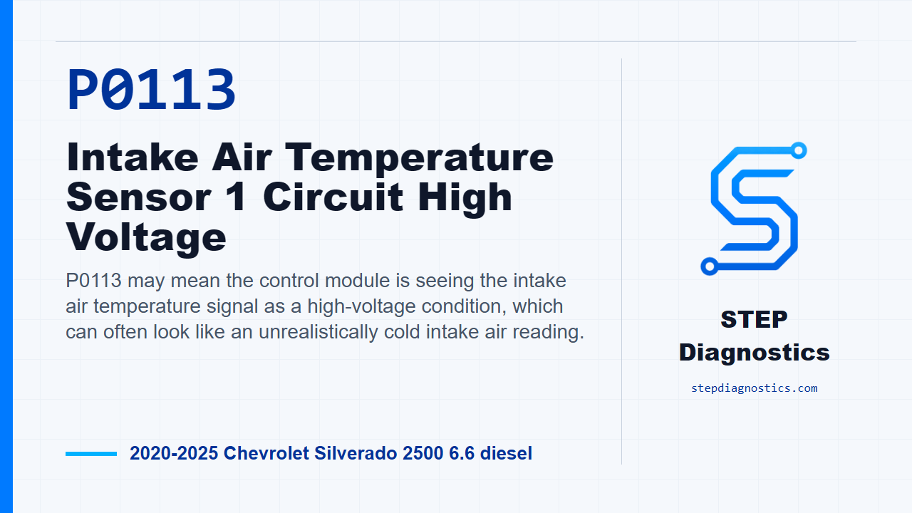
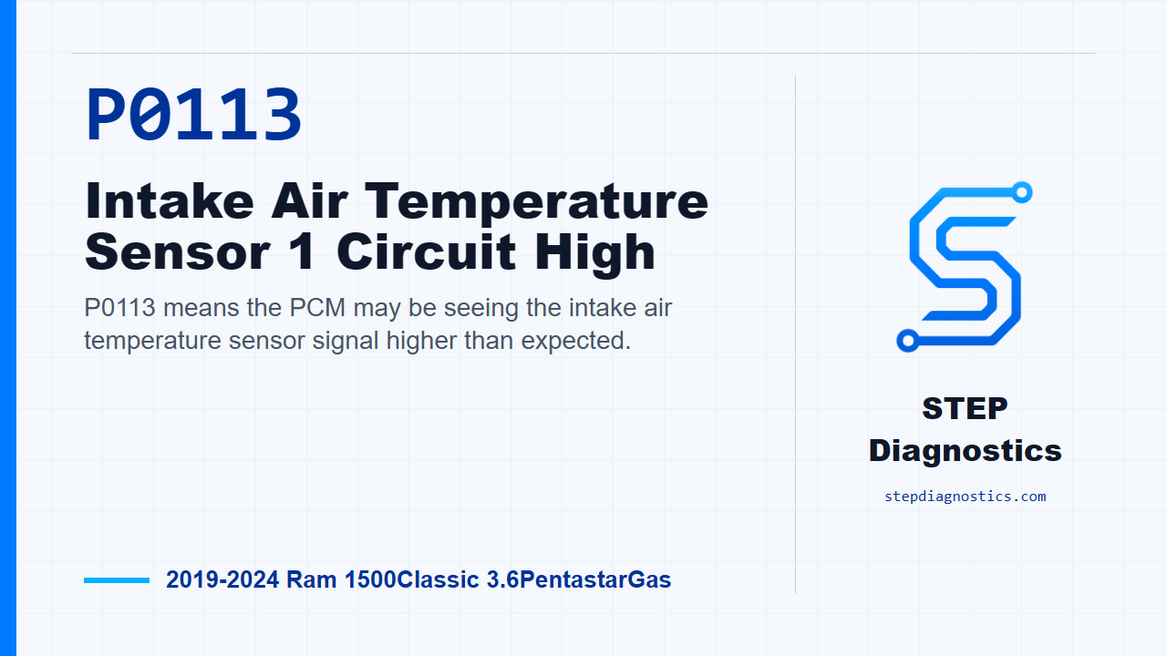
P0113 means the PCM may be seeing the intake air temperature sensor signal higher than expected.
What the vehicle may do
- The MIL may illuminate.
- The vehicle may run normally, or it may show possible drivability symptoms related to incorrect intake air temperature information.
Possible fault areas
- Possible IAT signal circuit fault.
- Possible sensor ground circuit fault.
- Possible IAT sensor fault.
- Possible PCM or PCM connection issue.
Diagnostic path
Opening context
For this Ram 1500 Classic with the 3.6 Pentastar, P0113 is an intake air temperature sensor circuit high code. In plain terms, the PCM may be seeing the IAT signal higher than it expects. The MIL will illuminate, and depending on the situation the truck may have no obvious complaint or may show air-temperature-related drivability symptoms. The likely fault areas are the IAT signal circuit, the sensor ground, the IAT sensor itself, and, after the circuit checks are proven out, the PCM. Start with the basic system checks before jumping into the code chart.
Monitor gate and set logic
Treat this as an electrical circuit diagnosis. The monitor runs with the ignition on and battery voltage greater than 10.4 volts. The code sets when the PCM detects the IAT sensor input voltage above approximately 4.9 - 4.95 volts depending on calibration for 2.24 seconds. Those values tell us the direction of the fault: the PCM is seeing a high signal, so the first checks are for unwanted voltage, then circuit integrity, then whether the PCM can recognize a simulated low signal.
Confirm the code status
Turn the ignition on. Use the scan tool to read DTCs and record them on the repair order. If P0113 is active or pending, continue with the circuit tests. If it is not active or pending, handle it as an intermittent condition instead of forcing a hard-fault path.
Check the IAT signal circuit for a short to voltage
Turn the ignition off and disconnect the IAT sensor harness connector. Turn the ignition back on and measure voltage on the (K21) IAT signal circuit at the IAT sensor harness connector. If the reading is above 5.2 volts, repair the (K21) IAT signal circuit for a short to voltage, then verify the repair and confirm the code stays gone. If the reading is not above 5.2 volts, move on to the resistance checks.
Check the IAT signal circuit for open or high resistance
Turn the ignition off. Use the 10436 GPEC diagnostic adapter at the engine harness side of the PCM C2 connector, but do not connect that adapter to the PCM. Also, do not probe the PCM harness connectors; probing them can damage the terminals and create a poor terminal-to-pin connection. Measure resistance in the (K21) IAT signal circuit between the IAT sensor harness connector and the GPEC adapter. If resistance is below 3.0 Ohms, continue. If it is not below 3.0 Ohms, repair the (K21) IAT signal circuit for an open or high resistance, then verify the repair and confirm the code stays gone.
Check the sensor ground circuit
Next, measure resistance in the (K915) sensor ground circuit between the IAT sensor harness connector and the GPEC adapter. If resistance is below 3.0 Ohms, go to the signal simulation check. If it is not below 3.0 Ohms, repair the (K915) sensor ground circuit for an open or high resistance, then verify the repair and confirm the code stays gone.
Check whether the PCM can read a simulated IAT signal
Turn the ignition off. Remove the GPEC adapter and reconnect the PCM C2 harness connector to the PCM. At the IAT sensor harness connector, install a jumper between the (K21) IAT signal circuit and the (K915) sensor ground. Turn the ignition on and read DTCs with the scan tool. If the matching low-circuit IAT code is active or pending with the jumper in place, replace the intake air temperature sensor, then verify the repair and confirm the code stays gone. If that low-circuit response is not active or pending, continue to the connector and harness inspection.
Inspect related connections before condemning the PCM
Disconnect all PCM harness connectors, any related in-line harness connections if equipped, and the related component connectors. Inspect the harness and component connectors, along with the male and female terminals, for installation problems, damaged locks, corrosion, water intrusion, weather seal damage if equipped, bent terminals, signs of overheating from a poor connection, terminals pushed back in the cavity, spread terminals, and poor terminal tension. Repair any conditions found. Then reconnect everything fully, make sure the connector locks are engaged, erase DTCs, and test drive or operate the vehicle under the monitored and set conditions. Read DTCs again. If P0113 returns after those checks, replace and program the PCM, then verify the repair and confirm the code stays gone. If it does not return, the wiring or poor connection problem has been repaired.
Closing takeaway
The clean path on P0113 is simple: prove the signal circuit is not shorted high, prove the signal and ground circuits have good continuity, simulate the sensor response, and only then move into connector integrity and PCM decisions. For more diagnostic training, visit stepdiagnostics.com.
Final check
This code is often approached as a sensor circuit diagnosis: confirm the code, test the signal and ground circuits, simulate the sensor response, inspect connections, and verify the repair.
For more guided automotive diagnostics, visit STEP Diagnostics.