What the EVAP system does
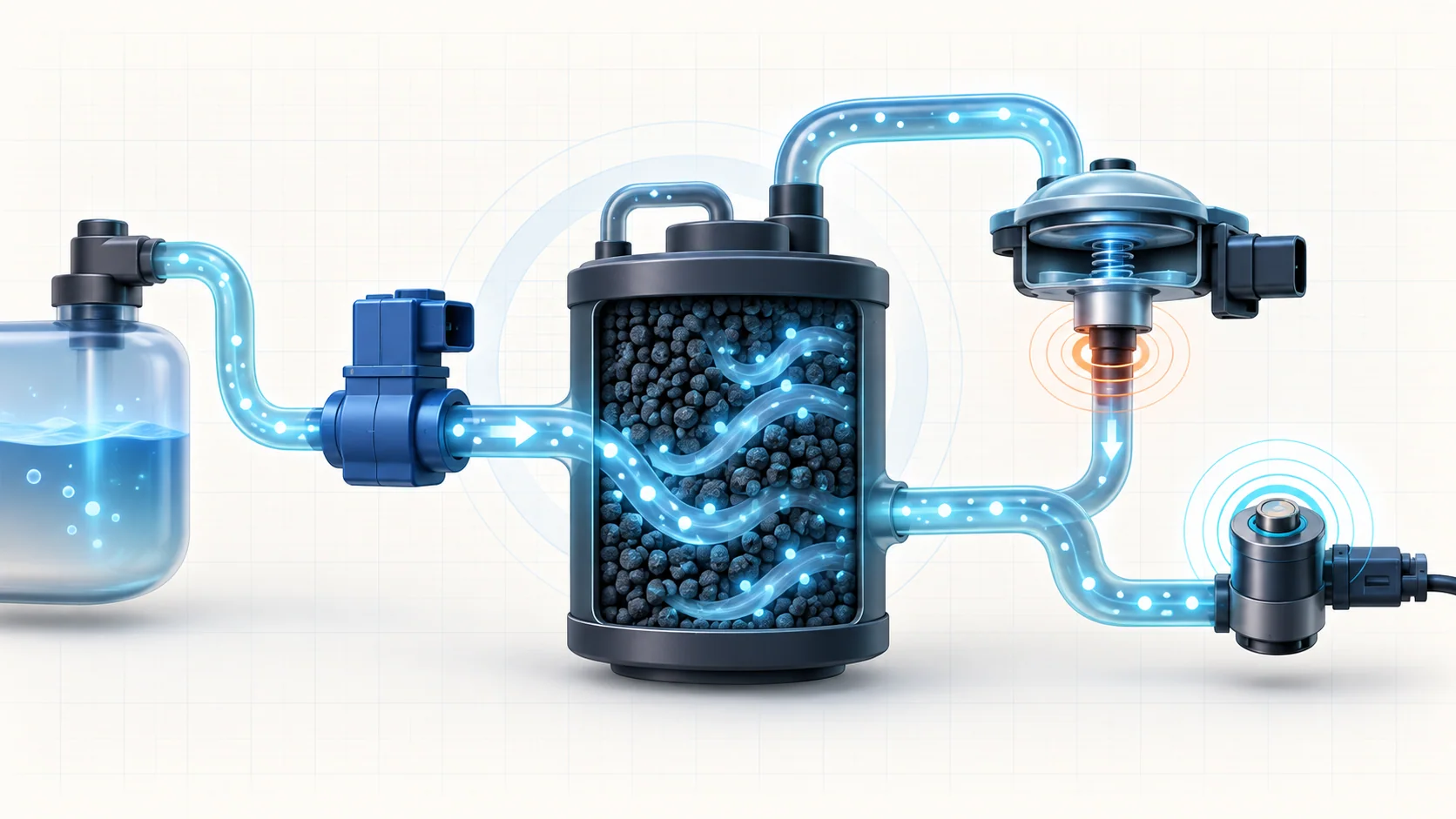
The evaporative-emissions (EVAP) system prevents gasoline vapor from venting directly to the atmosphere. On the 2019–2024 Ram 1500 Classic with the 3.6L Pentastar gasoline engine, the system stores vapor in a charcoal canister, meters it into the engine through a purge solenoid, and lets the powertrain control module (PCM) check whether the vapor path is sealed and responding as expected.
The linked STEP guides use the 2019–2024 vehicle grouping. Private service-information selections confirm the Ram 1500 Classic 4WD V6-3.6L configuration at both endpoints, while the detailed operation and diagnostic evidence reviewed for this overview comes from the exact 2024 application. Confirm the VIN, emissions label, fuel-filler design, calibration, component locations, and current service procedure before testing. Do not transfer connector details, scan-tool commands, or test limits between model years without verification.
An EVAP DTC reports a failed system check. It does not identify a failed component by itself. A leak, restriction, purge-flow fault, ESIM response problem, wiring issue, incorrect installation, or misleading operating condition can produce overlapping evidence.
The main functional sections
- Fuel tank and filler path: The tank, filler tube, cap or capless sealing unit, check valves, seals, and vapor tubes must contain fuel and route vapor without allowing liquid fuel into the vapor circuit.
- Charcoal canister: Activated charcoal stores fuel vapor when purge is not active.
- Fresh-air inlet and filter: Filtered atmospheric air enters the canister during purge. A blocked filter or vent path can create abnormal vacuum and misleading results.
- Purge solenoid and intake connection: The PCM controls the purge solenoid so intake-manifold vacuum can draw stored vapor into the engine at an appropriate rate.
- Evaporative System Integrity Monitor (ESIM): The ESIM contains pressure- and vacuum-responsive valves plus an electrical switch. The PCM uses its switch response to evaluate whether the system can reach and retain the required state.
- Fuel tank pressure sensor: On the exact application reviewed, the PCM does not use this sensor as the primary leak-decision input, but its signal is valuable diagnostic evidence because it shows how tank pressure changes during purge and decay testing.
- PCM diagnostics: The controller evaluates prerequisites, purge response, ESIM state, sealing behavior, circuit integrity, and whether the monitor completed under valid conditions.
How vapor storage and purge work
Gasoline naturally produces vapor in the fuel tank. The EVAP plumbing routes that vapor to the charcoal canister instead of releasing it outside. The canister holds hydrocarbons until the PCM decides the engine can consume them without disrupting fuel control or emissions operation.
When conditions are suitable, the PCM opens or pulses the purge solenoid. Intake vacuum then draws fresh air through the filtered side of the system, through the canister, and toward the intake manifold. The air carries stored fuel vapor into the engine, where it is burned.
Purge is both an emissions function and a controlled input to the engine. A purge valve that leaks when it should be closed can behave like an uncommanded vapor or vacuum path. A valve that does not open, a restricted hose, a blocked filter, or a disconnected line can keep the system from producing the expected pressure response even when no obvious external leak is present.
How the system checks for leaks
The PCM uses natural pressure and vacuum changes, controlled purge operation, and the ESIM switch to judge whether the closed vapor path behaves like a sealed system. During the intrusive general and large-leak evaluation, purge creates vacuum. The PCM then watches whether the ESIM changes state and how long the sealed system retains that state. The small-leak strategy behind P0456 is different: it accumulates evidence from valid engine-off natural-vacuum events rather than simply repeating the same purge-created-vacuum sequence.
Large-leak and small-leak codes describe different failed monitor results; they are not direct measurements of a visible hole. The small-leak monitor also depends on accumulated valid operating and engine-off events. Fuel level, ambient and fuel temperature, heat soak, recent refueling, altitude, other EVAP faults, and whether the truck completed the required soak can affect whether the monitor runs or whether a pressure-decay observation is trustworthy.
Extreme temperature change deserves special attention. Moving a hot or cold truck into a very different shop environment can make pressure change rapidly enough to hide a leak or make a sealed system appear unstable. Establish valid test conditions before interpreting the data.
What the related DTCs are telling you
| DTC | Diagnostic category | What it directs you to prove |
|---|---|---|
| P0440 | General EVAP response failure | Whether purge can create the required system response and whether the ESIM switch and its circuit report that response correctly |
| P0455 | Large-leak detection | Why the system loses the required state too quickly after purge created enough vacuum to close the ESIM switch |
| P0456 | Small-leak detection | Whether the system fails the more sensitive accumulated engine-off sealing check after prerequisite faults are addressed |
Work these codes as related evidence. P0440 can result from failure to create vacuum, a stuck-open ESIM switch, an ESIM circuit fault, a restriction, or a very large leak. P0455 and P0456 point toward different degrees of failed sealing evidence, but neither code proves the location or the failed part. Diagnose other EVAP circuit or response faults before treating a small-leak result as a simple hose leak.
What the driver or technician may notice
Common observations include:
- a malfunction indicator lamp with no obvious drivability complaint;
- an EVAP monitor that remains incomplete after codes are cleared;
- a code that returns only after an overnight soak or another valid monitor opportunity;
- fuel-vapor odor when an actual vapor leak is present;
- difficult refueling if the fresh-air or vent path is restricted;
- rough starting or unstable idle after refueling if purge flow is uncontrolled;
- visible damage or a loose connection near the filler, tank, canister, ESIM, or purge plumbing;
- companion purge, pressure-sensor, mixture, or electrical DTCs.
Fuel odor is a safety clue, not proof of the leak location. Stop and correct any liquid-fuel leak before continuing EVAP diagnosis.
Safety before testing
Work in a well-ventilated area away from flames, sparks, hot surfaces, and other ignition sources. Wear eye protection and follow the current procedure before opening a fuel or vapor connection. If the truck must be raised, support it at the approved lifting points; never rely on a jack alone.
Use only approved EVAP leak-detection equipment and the pressure source specified by the current procedure. Never use oxygen, an improvised smoke source, or unregulated pressure. Excess pressure can damage the tank, canister, valves, or sensors and can create a fire hazard. Keep liquid fuel and test fluid out of the charcoal canister and pressure-sensing path.
Common failure categories
1. Filler, tank, or service-seal leak
A damaged cap seal or capless unit, contaminated sealing surface, filler-neck fault, tank seam, fuel-pump seal, or disturbed service connection can leave the system open. Inspect the exact design fitted to the truck and check recent repair history.
2. Split, disconnected, or pinched vapor plumbing
Formed tubes and hoses can crack, rub through, disconnect, kink, or be routed incorrectly. Inspect the complete path rather than only the easiest hose to reach.
3. Purge-solenoid or vacuum-source fault
The purge solenoid may leak when commanded closed, fail to open, or respond intermittently. The intake connection or purge line may also be restricted. Separate electrical command, valve sealing, vacuum supply, and actual flow before replacing the solenoid.
4. ESIM, seal, or circuit problem
The ESIM may be installed incorrectly, leak at its mounting seal, have an internal valve problem, or fail to report its switch state because of wiring or connector trouble. A failed switch response does not automatically mean the system has an external leak.
5. Canister or fresh-air restriction
Dust, debris, liquid-fuel saturation, a pinched hose, or internal canister damage can restrict the fresh-air side. Excessive vacuum or refueling difficulty can be an important clue. If liquid fuel is found in the vapor path, determine why it entered before replacing affected parts.
6. Misleading pressure evidence or intermittent conditions
A biased pressure signal, unstable temperature, fuel movement, a marginal seal, debris that moves inside a valve, or harness motion can make the fault intermittent. Preserve the original evidence before disturbing the system.
A practical diagnostic sequence
1. Preserve the evidence
Scan all modules before clearing codes. Save freeze-frame or snapshot data, monitor status, fuel level, temperature, recent refueling history, and all active, pending, and stored DTCs. Ask when the lamp appeared and whether the truck was recently fueled or serviced.
2. Establish applicability and code priority
Confirm the VIN and emissions configuration, then check current service information and applicable bulletins. Address power, ground, purge-circuit, ESIM-circuit, or other prerequisite faults in the specified order.
3. Inspect the complete vapor path
Check the filler seal, tank-area plumbing, canister, ESIM, fresh-air filter, purge lines, intake connection, electrical connectors, and evidence of previous work. Look for liquid fuel, impact damage, rubbed hoses, dirt intrusion, pinched lines, and loose fittings.
4. Prove purge response before locating a leak
Use scan data and the directed purge test to decide whether the system can create the expected vacuum and whether the ESIM responds. Compare tank-pressure movement with purge command as supporting evidence. If the system cannot create vacuum, distinguish a very large opening from a purge-flow failure, restriction, or switch/circuit problem before reaching for a smoke machine.
5. Separate sealing from component behavior
Once the system can create the required state, determine whether it holds. If a leak is confirmed, use the approved whole-system test or divide the system at the specified point to isolate the tank/filler side from the canister/fresh-air/purge side. A smoke result proves only the path actually tested.
6. Test the supported branch
After isolation, test the suspected plumbing, seal, canister, purge solenoid, ESIM, pressure-sensor circuit, or related wiring with the current procedure. Use terminal-safe electrical methods and avoid replacing a component solely because its name appears in the DTC description.
7. Verify the repair
Restore every connection and run the applicable verification or monitor routine. Confirm that purge response is credible, the ESIM changes state as expected, the system retains the required state, no fuel odor or liquid leak remains, the monitor completes, and no related DTC returns.
Repair direction by confirmed cause
- Clean or repair the correct filler sealing surface, or replace a damaged cap or capless component, only when its fault is proven.
- Repair vapor tubes and hoses with the specified parts and routing; generic hose may collapse or react with fuel vapor.
- Replace a purge solenoid only after command, circuit, vacuum-source, sealing, and flow evidence supports it.
- Correct a restricted filter or vent path and identify the source of debris or liquid contamination.
- Repair ESIM wiring or sealing, correct installation, or replace the module only after the directed test isolates that branch.
- Repair tank, fuel-pump, canister, or service seals only after the leak is located.
- Do not replace the PCM until powers, grounds, circuits, inputs, outputs, and the directed diagnostic path support that conclusion.
Final takeaway
The Ram 1500 Classic EVAP system is a controlled vapor circuit. The tank and canister store vapor, the fresh-air path lets it move, the purge solenoid meters it into the engine, the ESIM provides sealing evidence, and the pressure sensor helps the technician understand the response. Diagnose those functions in order: preserve the monitor evidence, verify the whole vapor path, prove purge and ESIM response, confirm whether the system actually leaks, isolate the supported branch, and complete the exact post-repair verification before returning the truck to service.