Applicability basis: Authorized vehicle records confirm Ram 1500 Classic Truck 4WD applications with the 3.6-liter gasoline engine at the 2019 and 2024 endpoints. Detailed system operation and diagnostic evidence for this overview was verified on the 2024 application. Exact monitor thresholds, component arrangement, test values, scan-tool functions, connectors, and service procedures can vary by model year and calibration; use current service information for the truck being repaired.
What the misfire monitor actually measures
A misfire is a weak, late, incomplete, or missing combustion event. The powertrain control module (PCM) cannot see inside a cylinder and identify a failed coil, plug, injector, valve, or gasket. It infers combustion quality from the small acceleration each firing event should add to the crankshaft.
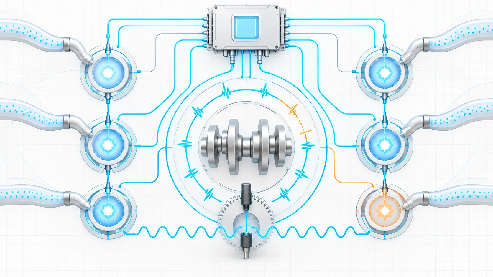
The crankshaft position (CKP) signal gives the PCM a detailed view of crankshaft position and rotational speed. When one cylinder contributes less torque than expected, crankshaft speed changes abruptly in that cylinder's part of the firing sequence. The PCM evaluates that variation with the current engine speed and load, then associates the disturbance with a cylinder-specific P0301-series code.
That distinction matters: the code reports the result of combustion, not the failed part. Ignition, fuel, air, compression, valve operation, cam timing, oil control, coolant entry, CKP signal quality, wiring, and even a severe non-combustion vibration can create a similar crankshaft-speed disturbance.
How ignition and combustion work together
The 3.6-liter engine uses PCM-controlled ignition coils at the cylinders. Each coil needs a sound power supply, a valid control command, an intact primary circuit, enough time to build energy, and a healthy secondary path through the boot and spark plug. When the PCM switches the coil, the magnetic field collapses and creates the voltage needed to fire the plug.
Spark is only one side of the event. The cylinder also needs the correct fuel quantity, a sealed air charge, adequate compression, and correctly timed valve motion. The CKP signal provides the crankshaft reference used to recognize the contribution event, while camshaft, load, temperature, airflow, fuel-control, and other inputs help the PCM coordinate combustion. A misfire monitor therefore sits at the intersection of several systems rather than acting as an ignition-component tester.
What the related DTCs tell you
| DTC | Diagnostic pattern | What it directs you to prove |
|---|---|---|
| P0301 | Cylinder 1 misfire pattern | Whether ignition energy, injector delivery, air sealing, compression, valvetrain condition, wiring, or another cylinder-local cause explains the result |
| P0303 | Cylinder 3 misfire pattern | Whether the fault follows a controlled component comparison or remains with cylinder 3 because of fuel, air, mechanical, signal, or circuit evidence |
| P0306 | Cylinder 6 misfire pattern | Whether the cylinder-specific evidence is caused by spark, fuel, sealing, valve operation, wiring, or a shared engine condition that affects cylinder 6 most strongly |
A repeatable cylinder-specific code often favors a local cause, while counts that move across several cylinders more often favor shared air, fuel, oil/timing, electrical, or mechanical conditions. Those are tendencies, not rules. A local intake leak can affect one cylinder most strongly, and one mechanical fault can disturb neighboring cylinders. Let the pattern organize testing without turning it into a parts decision.
What the driver or technician may notice
- a steady or flashing malfunction indicator lamp;
- rough idle, shaking, hesitation, or reduced power;
- a miss only when cold, hot, accelerating, cruising, or under heavy load;
- one cylinder repeatedly accumulating counts, several cylinders rising together, or counts shifting across the engine;
- a complaint after ignition, injector, intake, sensor, oil, timing, or engine work;
- little or no obvious symptom even though a pending code and stored operating record show that the monitor detected an event.
The operating condition matters as much as the cylinder number. A cold-start miss, a hot-idle miss, and a high-load miss should not begin with the same assumption.
During a severe misfire, the PCM may flash the MIL and temporarily disable fuel delivery to the affected cylinder to protect the catalytic converter. That protection can change what the technician observes after the initiating event. Preserve the stored record and original operating region before deciding that a rough idle is the root condition.
Common failure categories
Ignition energy is missing or weak
A worn, fouled, cracked, or incorrectly gapped spark plug; damaged boot; carbon tracking; moisture; weak coil; poor coil power; control-circuit fault; or loose terminal can reduce spark energy. Heat and cylinder pressure can expose a weakness that does not appear during a brief idle test.
A controlled coil or plug comparison can be useful when the parts are interchangeable and the current procedure permits it. Mark the components, change one variable, reproduce the same condition, and see whether the evidence follows. A swap is a test result, not permission to ignore plug-well contamination, terminal fit, power supply, or cylinder condition.
Fuel quantity or delivery is wrong
Contaminated or incorrect fuel, insufficient supply, pressure instability, a restricted injector, a leaking injector, or an injector circuit fault can cause a lean, rich, or inconsistent cylinder. Compare injector response or delivery using the applicable service method and equal starting conditions. Do not condemn an injector from resistance, sound, or one oxygen-sensor reading alone.
Incomplete combustion can leave oxygen in the exhaust and make feedback appear lean. Conversely, missing spark or excessive injector delivery can create rich-looking evidence. Interpret mixture data with misfire counts and the complete code set.
Air charge is uneven or uncontrolled
An intake or manifold leak, PCV or purge influence, restricted induction or exhaust, coolant entry, or another sealing problem can affect one cylinder, one bank, or the whole engine. The location of a leak matters; the cylinder with the highest count may be the most affected cylinder rather than the only affected cylinder.
Oil, valve timing, or valve operation is wrong
Low, contaminated, aerated, or incorrect oil; an unsuitable filter; pressure loss; cam-control problems; carbon buildup; worn cam lobes; damaged rocker arms; or weak or broken springs can change cylinder filling and combustion. Check oil level, condition, specification, service history, pressure concerns, and related cam or oil DTCs before repeatedly replacing ignition parts.
The cylinder cannot seal the charge
Valve leakage, valvetrain damage, ring or piston damage, head-gasket leakage, coolant entry, or another mechanical problem can produce a persistent misfire. Compression comparison is a screening test. A leakage test helps identify whether pressure escapes through the intake, exhaust, crankcase, cooling system, or an adjacent cylinder.
Crankshaft measurement or electrical control is unreliable
A CKP circuit problem, damaged target, incorrect sensor installation, poor connection, unstable cranking speed, electrical interference, coil power fault, coil-control circuit fault, or weak module power or ground can corrupt detection or prevent spark. Inspect terminal condition and use the correct breakout or back-probe method from current service information; forcing probes into control-module terminals can create a new fault.
Non-combustion vibration is confusing the monitor
Because the PCM evaluates crankshaft acceleration, a severely deteriorated belt, binding belt-driven accessory, or major wheel or braking vibration can sometimes complicate the result. Consider this only when the event pattern and current service information support it. It is not a shortcut around normal combustion checks.
A practical system-first diagnostic strategy
1. Preserve the evidence
Verify the exact year, engine, drivetrain, calibration, fuel, oil, recent repairs, and current service information. Save the complete module scan, confirmed/pending/history codes, freeze-frame or failure-record data, and cylinder misfire counts before clearing anything. Record whether the event occurs at start, idle, acceleration, cruise, deceleration, hot, cold, or under load.
2. Decide whether continued running is safe
A flashing MIL and heavy shaking can indicate a catalyst-damaging event. Reduce load and stop operation as soon as it is safe if the engine is shaking severely, power is sharply reduced, raw fuel is evident, or the lamp continues flashing. Abnormal mechanical noise, low oil pressure, or overheating also makes further reproduction unsafe.
3. Classify the pattern
Determine whether the same cylinder repeats, several cylinders share a pattern, or counts move across the engine. Compare current counts with the stored operating record. A stable single-cylinder event supports controlled local comparisons. A changing or multiple-cylinder event supports shared air, fuel, ignition-power, oil/timing, electrical, or mechanical checks first.
4. Prioritize related faults and shared conditions
Follow applicable service bulletins and resolve higher-priority fuel, ignition-circuit, crank/cam signal, airflow, oil-pressure, or variable-valve-timing faults as directed. Inspect battery condition, grounds, recent work, harness routing, connectors, intake joints, belts and driven accessories, oil level and condition, coolant level, and signs of contamination.
5. Reproduce the original condition with scan data
When safe, monitor cylinder counts and relevant fuel, airflow, oxygen-sensor, cam, and engine-speed information while recreating the stored condition. A smooth idle after clearing codes does not disprove a cold-start or high-load event. Remember that catalyst-protection fuel shutoff can make the post-event behavior look different from the initiating failure.
6. Separate ignition, fuel, air, and mechanical causes
Inspect the plug, coil, well, connector, and harness for the affected cylinder. Use one controlled component comparison at a time when permitted. If the evidence stays with the cylinder, continue with fuel quality and delivery, injector comparison, intake sealing, compression, leakage, carbon, and valvetrain checks rather than repeating ignition-part replacement.
7. Prove circuit integrity before condemning a controller
When spark or coil control is missing, separate coil power from the control path. Inspect connector engagement, locks, seals, corrosion, water intrusion, heat damage, pushed-back terminals, and terminal tension. Test opens, shorts, voltage supply, grounds, and command behavior through the approved service-information method. Controller replacement belongs at the end of a completed circuit and connection diagnosis, not at the beginning.
8. Verify the complete repair
Reconnect and secure every disturbed connector, coil, injector, hose, intake joint, shield, retainer, and ground. Complete any required setup procedure. Clear codes when directed, repeat the relevant monitor conditions, and reproduce the original operating region. Confirm that the complaint is gone, cylinder counts remain normal, and no related pending or confirmed DTC returns.
A cleared lamp, a short smooth idle, or a code that has not yet rerun is not repair verification.
Safety boundaries
Fuel can remain under pressure with the engine off. Relieve pressure and contain leakage using current service information before opening a hose, fitting, rail, or injector connection. Keep ignition sources away and use the specified protective equipment.
Running tests place the technician near the fan, belts, pulleys, hot exhaust parts, and secondary ignition voltage. Secure clothing, leads, and tools; stay out of the fan line; and use equipment rated for the test. Protect connector terminals with the specified adapters and probing method.
Final takeaway
On the 2019-2024 Ram 1500 Classic 3.6L Pentastar Gas, the misfire monitor watches the result of combustion through crankshaft-speed changes while cylinder ignition, fuel delivery, air sealing, valve motion, and compression create that result. P0301, P0303, and P0306 identify where the PCM associated the disturbance; they do not name the failed part.
Start with severity, the complete code set, stored operating evidence, and the cylinder pattern. Then use controlled tests to separate ignition power and control, secondary ignition, fuel, air, oil/timing, mechanical sealing, valvetrain condition, and crankshaft-signal causes. Finish by recreating the original condition and confirming that the monitor remains clean. The linked STEP DTC guides provide model-specific educational paths; current service information for the exact truck controls values, commands, connectors, disassembly, setup, and final verification.