Applicability basis: Verified vehicle records confirm Ram 1500 Classic 4WD applications with the 5.7-liter V8 at the 2019 and 2024 endpoints, supporting the public 2019-2024 model/engine range. Detailed system and diagnostic evidence for this overview was collected for a 2024 Ram 1500 Classic Truck 4WD V8-5.7L. Exact component locations, scan-tool functions, monitor conditions, pressure or vacuum limits, wiring details, equipment connections, and repair procedures must come from service information for the truck being repaired.
What the EVAP system does
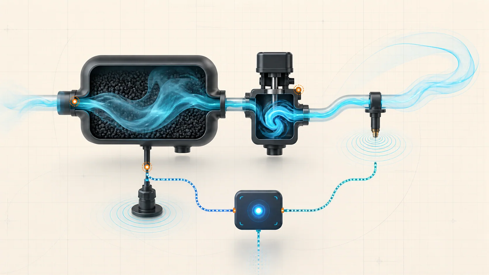
The evaporative-emissions system keeps gasoline vapor from venting directly into the atmosphere. Vapor produced in the fuel tank is routed to a charcoal canister, stored in activated carbon, and later drawn into the intake so the engine can burn it.
On this Ram, the system has three connected responsibilities:
- contain and route fuel vapor safely;
- meter stored vapor into the engine without upsetting combustion;
- test whether the vapor boundary seals and whether purge flow produces the expected response.
The powertrain control module (PCM) cannot see a cracked hose or a leaking seal directly. It commands system operation and evaluates switch or pressure feedback. A diagnostic trouble code therefore describes a monitor result, not a failed component by itself.
The main functional sections
- Fuel tank, filler, and tank vent hardware: These parts contain liquid fuel while allowing vapor to move through controlled passages. The exact filler and tank-valve arrangement can vary by configuration.
- Vapor lines and connections: Tubes link the tank, canister, integrity monitor, purge path, and intake. A leak, restriction, kink, incorrect connection, or liquid-fuel contamination can change system behavior.
- Charcoal canister: Activated carbon stores fuel vapor until the PCM allows purge. A damaged, saturated, contaminated, or restricted canister can affect both sealing and flow.
- Purge solenoid and purge path: On the verified 2024 configuration, the normally closed purge solenoid is pulse-width controlled. When opened under suitable conditions, it meters vapor from the canister toward the intake manifold.
- Evaporative System Integrity Monitor (ESIM): The exact 2024 system uses a vacuum-operated switch with passive pressure and vacuum relief functions. The PCM uses the ESIM switch state to judge leak-monitor behavior.
- Fuel tank pressure (FTP) sensor: The FTP sensor reports pressure or vacuum in the tank. On the verified 2024 strategy, it supports purge-performance diagnosis and technician testing, but the PCM uses the ESIM switch for the leak-monitor decisions discussed here.
- PCM, wiring, and connectors: The controller supplies commands and interprets feedback. An open circuit, poor ground, terminal problem, or misleading sensor signal can resemble a mechanical EVAP fault.
These parts form one system. Replacing the purge solenoid, ESIM, canister, or pressure sensor without proving the failed behavior can leave the original problem untouched.
How storage, purge, and self-testing work together
Vapor storage
Fuel vapor leaves the tank through controlled vent paths and enters the charcoal canister. The canister holds that vapor when purge is unavailable. Tank and filler valves help control vapor movement during driving, parking, refueling, and changes in temperature.
Controlled purge
After the engine reaches suitable operating conditions, the PCM can pulse the purge solenoid. Intake vacuum draws vapor from the canister toward the engine. The PCM varies purge flow rather than treating purge as a simple permanent ON or OFF command.
The verified 2024 strategy evaluates purge performance by watching FTP response as purge flow changes. Increasing purge should create a corresponding change in tank vacuum, and reducing purge should allow the response to move back in the expected direction. A wrong response can come from the purge path, vapor plumbing, a restriction, or pressure feedback; it is not automatic proof that the purge solenoid has failed.
Engine-off natural-vacuum monitoring
After shutdown, fuel temperature and vapor pressure change as the truck cools. In a sealed system, that natural pressure change can create enough vacuum to operate the ESIM switch. The PCM accumulates valid events and uses switch behavior to judge whether the system has demonstrated sealing.
Temperature, fuel level, soak time, and recent operation affect whether the monitor can run and how quickly the system changes. An EVAP code may therefore be intermittent and may not reproduce during a short shop visit.
Intrusive leak-size evaluation
When the required conditions are met, the verified 2024 strategy can use purge flow to draw the system into vacuum and observe the ESIM switch. If the switch never closes, the system may be unable to create the expected vacuum. If it closes and then opens too soon after purge is stopped, the system may be losing vacuum at a rate classified as a large leak.
That logic separates monitor outcomes, but it still does not locate the fault. A true opening, inadequate purge flow, a restriction, ESIM operation, wiring, or incorrect plumbing can change the result.
What the related DTCs are telling you
| DTC | Monitor category | What the technician needs to prove |
|---|---|---|
| P0440 | General EVAP system failure | Why the system did not obtain the expected ESIM-switch response during the test: inadequate purge vacuum, a large opening, a restriction, a switch/circuit problem, or another system fault |
| P0441 | Purge-system performance | Whether the purge path seals and flows as commanded and whether FTP feedback changes plausibly when purge increases and decreases |
| P0455 | Large-leak result | Why vacuum decayed too quickly after the system created enough vacuum to close the ESIM switch |
The categories overlap. A leaking purge solenoid can affect purge response and leak retention. A restricted fresh-air path can distort vacuum behavior. A damaged line or seal can prevent vacuum from developing or make it decay too quickly. A biased FTP signal can mislead a purge-performance test even though ESIM switch behavior controls the leak monitor.
What the driver or technician may notice
Many EVAP faults illuminate the malfunction indicator lamp without creating an obvious drivability complaint. Depending on the failure, the driver or technician may also encounter:
- an EVAP readiness monitor that remains incomplete;
- a fuel-vapor odor near the filler, tank, canister, vapor lines, or engine compartment;
- a fault that returns only after a particular fuel level, temperature change, cold start, or soak period;
- possible rough starting or unusual mixture behavior if purge flow occurs when it should not;
- refueling difficulty if the vapor or fresh-air path is restricted;
- multiple EVAP codes whose combination is more useful than any single code.
These observations are clues, not component tests. A normally driving truck can still have a leak, restricted path, purge problem, ESIM concern, circuit fault, or misleading pressure signal.
Common failure categories
1. The vapor boundary cannot seal
Possible leak points include filler sealing surfaces, hoses, tubes, quick connections, canister joints, tank-module seals, the tank, and the ESIM-to-canister interface. P0455 describes a leak-rate outcome; it does not identify where the opening is.
Inspect for recent service, disconnected or damaged plumbing, dirt at sealing surfaces, abrasion, cracks, and liquid fuel before connecting test equipment.
2. The system cannot create the expected vacuum
P0440 may be set when the expected ESIM closure does not occur. A very large opening is one possibility, but the purge solenoid may also fail to open, its vacuum supply may be missing, the purge tube may be restricted, or the ESIM switch or circuit may not report closure.
The first question is whether vacuum was actually created. That separates a leak or flow problem from a switch-feedback problem.
3. Purge flow is wrong
A purge solenoid can be electrically functional yet leak when closed, stick, become restricted, or fail to meter flow correctly. Plumbing restrictions, incorrect hose routing, canister problems, and pressure-feedback faults can produce a similar P0441 result.
Prove both sides of the function: the valve must seal when commanded closed and create a controlled, believable response when commanded open.
4. ESIM operation or mounting is wrong
The ESIM combines switch and passive relief functions. Contamination, internal leakage, incorrect orientation, a damaged mounting seal, or a switch/circuit fault can affect the monitor. Do not condemn the ESIM from a code alone; compare actual system vacuum with switch state.
5. The vent or vapor path is restricted
A blocked fresh-air inlet, damaged filter hose, contaminated canister, kinked tube, or stuck valve can create excessive or abnormal vacuum. A restriction can also cause refueling complaints and can distort leak-test results.
6. FTP feedback is not trustworthy
Purge-performance diagnosis depends on a believable FTP signal. Establish its atmospheric baseline and verify that it moves in the correct direction during a known system change. An unexpected scan value can come from the sensor, its circuits, trapped tank pressure, a restricted path, or the way the test was connected.
Safety before testing
Gasoline vapor is flammable. Work in a well-ventilated area, keep sparks, flame, hot surfaces, and other ignition sources away, and follow the applicable personal-protection and fuel-system precautions. Stop if liquid fuel is leaking.
Use only approved EVAP leak-detection equipment and connect it exactly as current service information directs. Do not apply raw shop air or another improvised pressure source directly to the tank or vapor system. The approved tester may use a specified regulated supply internally, but that does not authorize bypassing its controls. Never exceed the pressure or vacuum limits for the exact truck.
Support the vehicle correctly before working underneath it. Route test leads and hoses away from belts, fans, exhaust components, and moving parts during running tests.
A practical system-first diagnostic strategy
Step 1: Confirm the exact truck and preserve evidence
Verify model year, engine, drivetrain, tank configuration, fuel-fill design, and installed EVAP hardware. Record confirmed, pending, and history DTCs plus freeze-frame or failure-record data before clearing anything. Note fuel level, recent refueling, outside temperature, soak time, recent repairs, and whether the complaint follows a cold start or shutdown.
Step 2: Diagnose related circuit and prerequisite codes first
Check for purge-solenoid, ESIM, FTP-sensor, fuel-level, temperature, voltage, or other related DTCs identified by the applicable procedure. Performance diagnosis is useful only when the PCM can command the system and trust its feedback.
Step 3: Classify the monitor result
Use the code family to choose the first question:
- P0440: Did the system fail to create vacuum, or did the ESIM fail to report it?
- P0441: Did commanded purge produce the correct FTP response, and did the purge path seal when closed?
- P0455: After vacuum was created, where did the system lose it?
This classification prevents every EVAP code from becoming the same smoke-test routine.
Step 4: Inspect before disturbing the system
Inspect the filler interface, accessible tank and canister connections, purge plumbing, ESIM mounting, fresh-air path, wiring, and recent service areas. Look for loose connections, chafe, impact damage, kinks, debris, contamination, incorrect routing, and liquid fuel. Preserve the original position of an intermittent connector or hose before moving it.
Step 5: Establish a credible FTP baseline
Vent the system only by the method specified for the truck, allow pressure to stabilize, and compare the FTP reading with the applicable specification. Then verify that the signal changes in the expected direction when a known pressure or vacuum condition is applied through the approved procedure.
Resolve a biased or unresponsive pressure signal before using it to judge purge performance.
Step 6: Compare purge command, pressure response, and ESIM state
Use the supported bidirectional controls and data list for the exact truck. Determine whether the purge solenoid seals when off, whether controlled purge creates tank vacuum, and whether the ESIM switch changes state when the system actually reaches vacuum.
Interpret the signals together:
- pressure changes but ESIM state does not: inspect switch operation and circuits;
- neither pressure nor ESIM state changes: investigate purge supply, purge flow, a very large opening, or a major restriction;
- vacuum appears before purge is commanded: test for unwanted purge flow;
- pressure response is implausible: verify FTP and plumbing before replacing a valve.
Use exact command limits and time limits from current service information. Do not create excessive tank vacuum while experimenting with bidirectional controls.
Step 7: Leak-test and isolate only after setup is proven
Calibrate the approved leak detector, use the specified connection point, and place the system in the required state. A flow or pressure result establishes whether the system is sealed; smoke helps locate an opening. Those are related but different tasks.
If the complete system fails, follow the applicable procedure to divide the tank side from the canister, purge, and fresh-air side. Check every accessible connection and sealing point. A visible smoke exit identifies an opening, but absence of visible smoke does not prove that purge flow, ESIM operation, FTP feedback, and monitor logic are correct.
Step 8: Repair the proven fault and verify the result
The repair may involve restoring a hose or connection, cleaning a sealing surface, correcting routing, repairing a circuit, replacing a valve that failed a directed test, servicing a damaged tank or canister seal, or replacing an internally leaking component. Follow the exact removal, installation, orientation, seal, and fastener procedure.
After reassembly, repeat the test that proved the failure. Clear codes only after preserving evidence, run the applicable verification routine or monitor conditions, and recheck pending codes and readiness.
A cleared MIL with an incomplete EVAP monitor is not a verified repair.
Avoid the EVAP parts cannon
P0440, P0441, and P0455 share components but describe different failed behaviors. The purge solenoid may fail to seal, fail to flow, or be completely healthy while a hose leaks. The ESIM may fail mechanically or electrically, or it may correctly report a system that cannot hold vacuum. The FTP sensor may mislead purge diagnosis without controlling the leak monitor itself.
Make each test answer one question:
- Is the vapor boundary sealed?
- Can controlled purge create vacuum?
- Does the purge path seal when commanded off?
- Does FTP feedback match a known system state?
- Does the ESIM switch agree with actual vacuum?
- Is the fresh-air path open and unrestricted?
- Does the circuit support the commanded component state?
Once the failed section is proven, use the linked STEP guide for code-specific educational context and current service information for exact commands, values, equipment setup, repair instructions, and final verification.
Final takeaway
On the 2019-2024 Ram 1500 Classic 5.7 HEMI Gas, EVAP diagnosis depends on understanding two different feedback paths. The verified 2024 strategy uses ESIM switch behavior to evaluate system sealing and FTP response to evaluate purge performance. P0440, P0441, and P0455 therefore start with different questions even though they share the same vapor system.
Preserve the stored evidence, classify the monitor result, inspect the system, establish a trustworthy pressure baseline, compare purge response with ESIM state, and leak-test only after the setup is proven. That sequence turns a broad EVAP code into a small set of testable sections.