What the oil pressure monitoring system does
The oil pressure monitoring system helps the powertrain control module (PCM) decide whether the engine oil pressure signal is believable. It links the engine's pressurized lubrication system, the engine oil pressure (EOP) sensor and its wiring, PCM diagnostic logic, and the warning information presented to the driver.
Private service-information targets confirm 2019 and 2024 Ram 1500 Classic 4WD 5.7L applications, while the linked STEP guides use the 2019-2024 educational grouping. The detailed system descriptions, tests, and repair procedures reviewed for this overview are from the exact 2024 application. Confirm the VIN, engine application, calibration, oil specification, sensor design, wiring, and current service information before testing. Exact values and procedures can differ within the grouped range.
An oil pressure DTC does not identify a failed part by itself. A low electrical signal does not prove that mechanical pressure is low, and a plausible scan value does not prove that the lubrication system is safe. Diagnosis must establish two facts separately: what pressure the engine is actually producing and whether the sensor circuit reports it truthfully.
The main functional sections
- Oil supply and pressure: Oil level, condition, viscosity, pickup flow, pump operation, pressure regulation, filtration, internal clearances, and leakage all affect the pressure available to lubricate the engine.
- Engine oil pressure sensor: The EOP sensor converts pressure at its measurement point into an electrical signal for the PCM.
- Reference, signal, and sensor-ground circuits: The exact 2024 sensor uses a PCM reference, a signal circuit, and a PCM-supplied sensor ground. Opens, shorts, high resistance, poor terminal contact, or shared-reference faults can create a false reading.
- PCM monitoring: The PCM compares the pressure-related signal with engine operating conditions. It can set a performance code when the reported behavior is implausible or a circuit code when the electrical input is too low.
- Driver warning and scan evidence: The driver may see an oil-pressure warning, a malfunction indicator lamp, or both. The technician can compare DTC status and scan data with an independent mechanical-pressure result.
- Mechanical verification equipment: When the applicable procedure requires it, a correctly installed mechanical gauge provides independent evidence that separates an indication fault from a real lubrication-pressure problem.
How mechanical pressure and the electrical signal work together
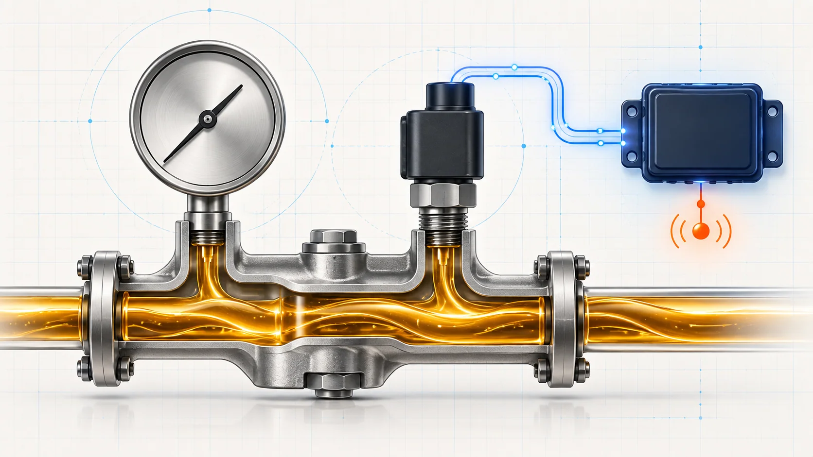
The 5.7L lubrication system is a pressure-feed, full-flow-filtered system. With the engine running, the pump moves oil through the lubrication passages. The EOP sensor reports a pressure-related voltage to the PCM through its signal circuit, using the PCM's reference and sensor-ground circuits.
The PCM does not directly see the pump, pickup, bearings, or oil passages. It sees the sensor signal and evaluates that signal against operating conditions. A genuine loss of oil pressure can therefore produce a low or implausible input, but so can a blocked sensor port, a biased sensor, damaged wiring, poor terminal contact, or a shared reference problem.
That is why a pressure complaint cannot be solved from one data point. The scan value, DTC type, oil level and condition, engine noise, connector condition, and mechanical gauge result must agree. When they do not agree, the disagreement is diagnostic evidence.
What P0521 and P0522 are telling you
| DTC | Diagnostic category | What it directs you to prove |
|---|---|---|
| P0521 | Engine oil pressure sensor performance | Whether the signal is plausible for the operating condition and whether the cause is actual lubrication pressure, engine mechanical condition, sensor response, a restricted sensor passage, reference/signal/ground integrity, connector quality, the sensor, or the PCM |
| P0522 | Engine oil pressure sensor circuit low | Whether the low input comes from a shared reference issue, an open or shorted circuit, connector or terminal damage, the sensor, or the PCM |
P0521 is not an instruction to replace the sensor. P0522 is not proof that the oil pump has failed. Treat each code as a test direction and use the complete scan to decide which branch has priority.
What the driver or technician may notice
Possible observations include:
- an oil-pressure warning or message;
- a malfunction indicator lamp with P0521, P0522, or companion reference-voltage codes;
- a warning that appears only after warm-up, at idle, or under another repeatable operating condition;
- scan data that changes when the harness or connector is disturbed;
- abnormal valvetrain or lower-engine noise when pressure is genuinely inadequate;
- no obvious drivability complaint even though the PCM has detected an electrical fault;
- disagreement between scan data, a warning, and a mechanical gauge result;
- evidence of recent oil service, sensor replacement, engine work, contamination, or leakage.
The absence of noise does not prove pressure is safe. Conversely, an electrical warning alone does not prove internal engine damage.
Safety before testing
If an oil-pressure warning is accompanied by abnormal mechanical noise, confirmed absent pressure, severe leakage, or another sign of lubrication loss, shut the engine off. Do not continue running it merely to collect more data. Continued operation can cause rapid engine damage.
Engine oil and nearby components can be hot. Wear eye protection and suitable gloves, keep clear of belts and fans, and use a gauge, hose, and adapter rated and secured for the procedure. Check for leakage before raising engine speed, and never place your body in the path of pressurized oil.
Use terminal-safe test methods. Do not spread connector terminals, probe a controller connector in a way the service information prohibits, or apply power to a sensor circuit unless the exact directed test requires it. Restore battery connections, connectors, and harness routing exactly as specified after service.
Common failure categories
1. Oil level, condition, viscosity, or leakage
An incorrect oil level, unsuitable viscosity, degraded or aerated oil, fuel or coolant contamination, or external leakage can affect real pressure. Verify the basics using the procedure and oil specification for the exact truck. Preserve evidence of contamination or loss before correcting it because that evidence may identify the root cause.
2. Genuine mechanical pressure problem
A restricted pickup, pump or pressure-regulation problem, excessive internal leakage, worn clearances, filter or passage restriction, or another mechanical fault can produce inadequate pressure. A mechanical gauge test under the specified conditions is the deciding evidence. If pressure is absent, stop the engine and investigate the mechanical supply path rather than continuing an electrical test.
3. EOP sensor or sensor-port fault
The sensor can be biased, intermittent, internally open or shorted, or unable to respond correctly. Its oil passage can also be restricted. Prove actual pressure and circuit behavior before replacement. After replacement, use the correct sealing method, inspect for leakage, and verify that the signal behaves credibly.
4. Connector or harness fault
Poor locking, backed-out or spread terminals, corrosion, oil or water intrusion, chafing, heat damage, an open, a short to ground, or high resistance can distort the signal. Inspect the connector before disconnecting it, then follow the exact circuit tests without damaging terminals.
5. Reference or sensor-ground problem
A shared reference or ground fault can affect more than the EOP input. Review the complete code list and compare related sensor behavior before isolating one component. Repair the circuit that fails the test rather than replacing every sensor attached to it.
6. PCM interpretation or connection concern
The PCM evaluates the sensor signal, but controller replacement belongs at the end of a documented path. Prove mechanical pressure, the sensor, reference, signal, sensor ground, terminal contact, and intermittent conditions first.
A practical diagnostic workflow
1. Preserve the evidence
Record all module DTCs, status, freeze-frame or snapshot data, warning messages, engine temperature, engine speed, oil level and condition, and the circumstances that produced the complaint. Note recent oil service, engine repair, sensor work, harness work, collision damage, or jump-start history.
2. Decide whether it is safe to run the engine
Check oil level and severe leakage before restarting. If the engine is noisy, the warning is accompanied by signs of mechanical distress, or pressure loss is strongly suspected, stop and move to the applicable mechanical inspection or pressure-test procedure.
3. Scan the complete vehicle
Do not read only P0521 or P0522. Shared reference, power-supply, communication, or other sensor codes can change diagnostic priority. Save the data before clearing anything and determine whether the fault is active, pending, stored, or intermittent.
4. Inspect the basics
Verify oil level and condition, then inspect the sensor area, connector, accessible harness, and signs of leakage or recent disturbance. Look for a condition that changes with heat, vibration, engine movement, or harness position.
5. Separate actual pressure from the signal
For a performance complaint, establish that the engine and lubrication system are mechanically sound before treating the fault as purely electrical. Use the exact wiring diagram and directed tests to evaluate reference, signal, and sensor-ground behavior. If actual pressure remains uncertain—or the procedure directs it—perform the exact mechanical gauge test and compare the results under matching conditions.
6. Use the DTC category to choose the branch
P0521 requires a plausibility decision: pressure, sensor response, and circuit behavior must agree. P0522 directs attention to a low electrical input, so shared-reference codes, connector condition, shorts, opens, and signal response take priority. Neither path justifies parts replacement until the evidence isolates the cause.
7. Repair only the proven cause
Repair a terminal or wire that fails inspection or testing, replace a sensor that fails directed evaluation, clear a restricted sensor passage when the procedure supports it, or continue with the mechanical engine procedure when the independent pressure result is wrong. Pump inspection and replacement are mechanical repair decisions, not conclusions drawn from the DTC name.
8. Verify the repair
Restore all connectors and battery connections, confirm correct oil level and leak-free operation, clear DTCs when appropriate, and repeat the conditions that produced the fault. Verify credible scan data, no returning codes or warning, and acceptable mechanical pressure when it was measured or the procedure requires it.
What not to do
- Do not keep a noisy engine running with an oil-pressure warning.
- Do not assume a low sensor signal proves low mechanical pressure.
- Do not assume a plausible scan value replaces a mechanical test when the procedure requires one.
- Do not apply generic pressure specifications across the full 2019-2024 range.
- Do not pierce wires, spread terminals, or apply battery voltage to sensor or PCM circuits.
- Do not replace the sensor, PCM, or oil pump without evidence that isolates that component or system.
- Do not clear codes before saving the conditions that made the fault appear.
The diagnostic principle to remember
Treat oil-pressure diagnosis as two linked proofs: actual mechanical pressure and truthful electrical reporting. Establish which proof fails before choosing a repair. This protects the engine, prevents an electrical fault from being mistaken for internal damage, and prevents a real lubrication problem from being dismissed as “just a sensor.”