What this code means
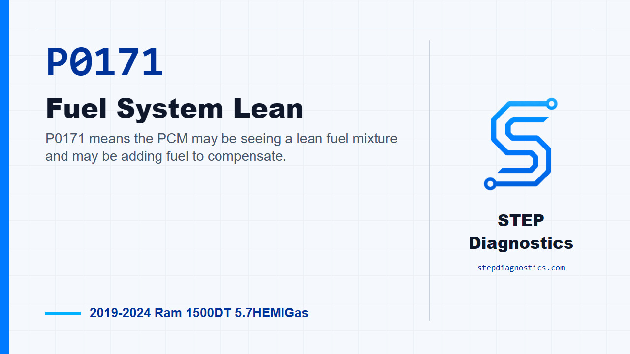
P0171 means the PCM may be seeing a lean fuel mixture and may be adding fuel to compensate.
What the vehicle may do
- The MIL may illuminate.
- Stop/start may be disabled while the code is active.
- The vehicle may show lean-condition drivability symptoms.
Possible fault areas
- Possible fuel delivery concerns.
- Possible unmetered air or vacuum leaks.
- Possible purge flow concerns.
- Possible exhaust leaks.
- Possible MAP sensor information concerns.
- Possible upstream oxygen sensor wiring or sensor concerns.
Diagnostic path
Opening context
On this Ram 1500 with the 5.7 HEMI, P0171 is a lean fuel-system fault. In plain terms, the PCM may be seeing fuel correction move lean enough that it has to add fuel beyond where it expects to be. The truck may turn the MIL on, and if it has stop/start, that system may be disabled while the code is active. A lean code like this can come from several possible areas: fuel delivery, unmetered air, purge flow, exhaust leaks, MAP sensor information, upstream oxygen sensor wiring, the oxygen sensor itself, or in the end, the PCM. But don’t start with the oxygen sensor just because it is in the code path. This fault is more often driven by a mechanical, fuel, or air-handling issue, so work through it in order.
Monitor gate and setting logic
Before chasing the fault, make sure the basic system checks are done. The monitor is only meaningful when the engine is running in closed-loop fuel control and the gate conditions are met: battery voltage above 11.0 volts, barometric pressure greater than 75 kPa, ambient temperature above -7°C (20°F), fuel level greater than 12%, and altitude below 2590.8 m (8500 ft.). The setting logic is fuel-trim based. When the combined short-term and long-term fuel corrections are greater than a calibrated threshold, generally 133%, with 100% being nominal, the fail timer starts. After approximately 30 seconds of fail time, the diagnostic fails. The broader emissions threshold behind this monitor is when emissions exceed 1.5 times any of the standards.
Confirm the code returns
Start by reading DTCs in all ECUs, and record the codes and environmental data. Save a vehicle scan report and the related recorded data for the job record. Then erase all DTCs, turn the ignition off for a minimum of 10.0 seconds, turn the ignition back on, and operate the vehicle under the same monitor and captured conditions that set the fault. Read DTCs again. If P0171 returns, continue with the diagnostic path. If it does not return, treat it as an intermittent condition and do not force a repair that the vehicle is not currently proving out.
Check for supporting fuel or air-handling faults
Next, look back at the recorded DTCs. If other active or pending faults are present in the fuel or air-handling systems, handle those first. They can be the reason this lean code is setting. If there are no active or pending fuel or air-handling faults, move on to the P0171-specific checks.
Work through MAP, fuel delivery, and fuel content
Now check MAP sensor operation. If that test finds a MAP-related problem, repair that issue and verify the repair. If MAP operation checks out, check the fuel delivery system. If a fuel delivery problem is found, repair that issue and verify the repair. If fuel delivery checks out, check the ethanol content in the gasoline. If the gasoline has an ethanol-content issue for this vehicle, repair that fuel-related issue and verify the repair. If no issue is found there, continue to the mechanical checks.
Mechanical and air-leak checks
With the ignition off, check the mechanical and air-side causes. The air induction system needs to be free of leaks. Check the engine and vacuum hoses for vacuum leaks, including the power brake booster. For the booster, monitor engine speed and vacuum while pinching the vacuum hose going to the booster. If a fuel injector is suspected of being plugged or restricted, remove the fuel rail with the injectors intact, energize the fuel pump to maintain fuel pressure in the rail, actuate the suspect injector or injectors with the scan tool, and compare the spray pattern with the others. Also check that the purge flow system flows freely with no leaks or restrictions, and inspect the hose and connections between the purge solenoid and the intake manifold. Engine compression also has to be within specifications. If any engine mechanical problem is present, repair that issue and verify the repair. If no mechanical problem is present, keep going.
Exhaust leak check
After the mechanical checks, check the exhaust system for leaks. An exhaust leak can affect what the upstream oxygen sensor reports and contribute to a lean calculation. If a problem is found, repair the exhaust-related issue and verify the repair. If no exhaust problem is found, move into the upstream oxygen sensor circuit checks.
Upstream oxygen sensor wiring check
For the upstream oxygen sensor wiring check, disconnect the upstream O2 sensor harness connector and the PCM C2 harness connector. Connect the GPEC Diagnostic Adapter 10436 to the engine-harness side of the PCM C2 connector. Do not connect the adapter to the PCM. Also, do not probe the PCM harness connectors; probing them can damage the PCM terminals and create a poor terminal-to-pin connection. With the adapter in place, check the upstream O2 sensor circuits for a short to ground, and for an open or high resistance between the O2 sensor connector and the adapter. If a circuit problem is found, make the appropriate wiring repair and verify the repair. If no circuit problem is found, continue to the sensor retest step.
Oxygen sensor replacement and retest
At this point in the path, replace the upstream O2 sensor, then reconnect the Bank 1 upstream O2 sensor connector and the PCM harness connectors. Turn the ignition on, erase the DTCs, and operate the vehicle under the captured or monitor conditions that set P0171. If the code does not return, the upstream O2 sensor replacement repaired the fault, and the repair still needs to be verified. If P0171 does return, continue to the connection checks before condemning the module.
Connection checks before PCM replacement
Before going any farther, perform any applicable service bulletins. Then disconnect all PCM harness connectors, any related in-line connectors if equipped, and the related component connectors. Inspect the harness and component connectors, including male and female terminals, for proper connector installation, damaged locks, corrosion, water intrusion, weather-seal damage if equipped, bent terminals, signs of overheating from a poor connection, terminals pushed back into the cavity, spread terminals, and proper terminal tension. Repair anything found. Reconnect the PCM connectors, in-line connectors if equipped, and related component connectors, making sure each one is fully seated and each lock is fully engaged. Erase the DTCs, test drive or operate the vehicle under the monitor and setting conditions, then read DTCs again. If P0171 does not return, the wiring or poor connection problem has been repaired. If it does return after all of that, the path supports replacing and programming the PCM, followed by repair verification.
Verification and closing takeaway
Keep verification separate from the testing. Any time one of these checks finds and repairs a problem, verify the repair and confirm the code stays gone under the conditions that originally set it. The takeaway is simple: P0171 is a lean calculation, not an automatic oxygen sensor call. Prove the operating conditions, clear out related fuel and air-handling faults first, check the mechanical and fuel causes, then move into the O2 wiring, sensor, connections, and PCM only in that order. For more diagnostic training, visit stepdiagnostics.com.
Final check
P0171 is often best approached as a lean-system diagnosis first, then an oxygen sensor circuit diagnosis only after the earlier checks pass.
For more guided automotive diagnostics, visit STEP Diagnostics.