Quick answer
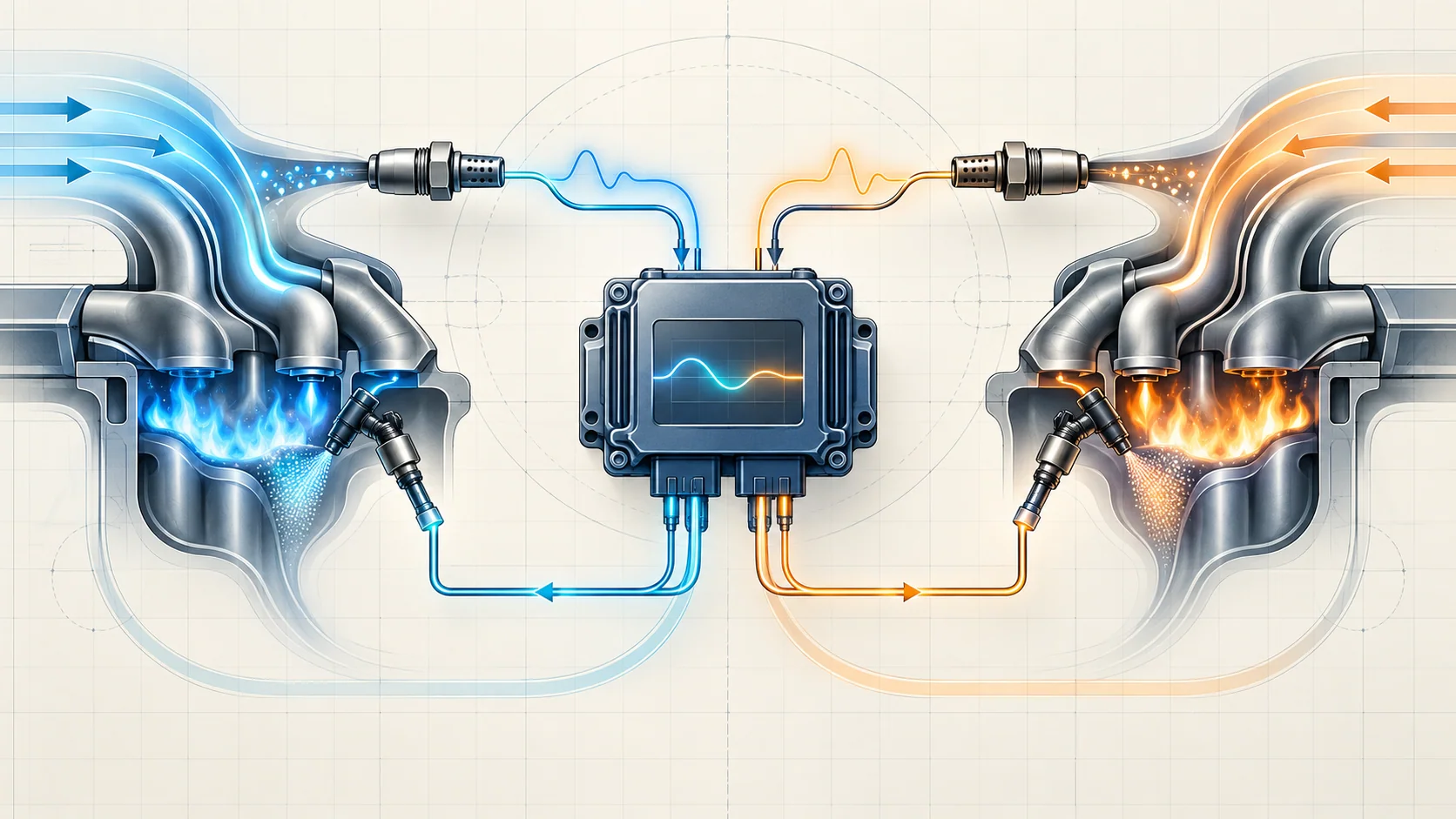
The powertrain control module (PCM) calculates a starting fuel command, watches upstream oxygen-sensor feedback, and changes injector delivery to keep the mixture near its target. Short-term fuel trim records immediate correction; long-term fuel trim carries a learned correction when the same bias persists. P0171 and P0174 mean the PCM has had to add too much fuel on Bank 1 or Bank 2. P0172 and P0175 mean it has had to remove too much fuel. None of these codes, by itself, proves that an oxygen sensor, injector, fuel pump, or PCM has failed.
Applicability and service-information boundary
This overview applies to the 2019-2024 Ram 1500DT 5.7 HEMI Gas configuration. Authorized vehicle records confirm Ram 1500 Truck 4WD applications with the 5.7-liter eTorque MHEV powertrain at the 2019 and 2024 endpoints. Detailed system-operation and diagnostic evidence for this overview was verified on the exact 2024 application.
Calibration, monitor conditions, fuel specifications, pressure values, wiring, sensor design, component access, scan-tool functions, and repair procedures can change by year and equipment. Use current service information for the exact truck whenever a test requires a value, connector, command, special tool, fuel-pressure procedure, or component-removal step.
What the air/fuel control system is trying to do
The engine needs a controlled relationship between the air entering each cylinder and the fuel delivered by the injectors. The PCM begins with engine speed, load, manifold pressure, throttle position, temperatures, and other operating inputs. It calculates injector delivery, then checks the combustion result through exhaust oxygen feedback.
In closed-loop operation, the upstream oxygen sensors report whether combustion is trending lean or rich. The PCM adjusts injected fuel quantity to reduce the error between the desired and observed mixture. Downstream oxygen-sensor information has a different role: it helps the controller monitor and refine catalyst-related behavior. Upstream and downstream data should not be treated as interchangeable.
The system is a feedback loop, so the reporting component is not automatically the cause. A believable lean exhaust signal can be created by unmetered air, inadequate delivery, an exhaust leak, purge flow, or a weak cylinder. A believable rich signal can be created by excessive fuel delivery, a leaking injector or purge valve, restricted airflow, fuel contamination, or a mechanical problem.
How short-term and long-term fuel trim work
Fuel trim is the PCM's correction to its base fuel command.
- Short-term fuel trim responds quickly to current oxygen-sensor feedback and changing operating conditions.
- Long-term fuel trim stores a broader learned correction when a bias persists long enough to be treated as recurring rather than temporary.
- Positive correction means the PCM is adding fuel because feedback indicates a lean result.
- Negative correction means the PCM is removing fuel because feedback indicates a rich result.
Short-term and long-term trim must be considered together. A short-term value near center does not prove the system is healthy if long-term trim is carrying a large learned correction. A normal-looking idle snapshot also does not disprove a fault that occurred at cruise, under load, during purge, or at another temperature.
The PCM's monitor runs only when its enabling conditions are satisfied. Freeze-frame or failure-record data therefore matters: it tells the technician where in the operating range the correction exceeded the calibrated limit.
Why bank comparison is useful on the 5.7-liter V8
This engine has two cylinder banks with separate upstream feedback paths. The four linked codes identify both direction and bank:
| DTC | Fuel-control result | Diagnostic meaning |
|---|---|---|
| P0171 | Bank 1 lean correction | The PCM is adding excessive fuel correction on Bank 1; prove why before replacing a part |
| P0172 | Bank 1 rich correction | The PCM is removing excessive fuel correction on Bank 1; prove whether the rich result is real or input-driven |
| P0174 | Bank 2 lean correction | The PCM is adding excessive fuel correction on Bank 2; compare it with Bank 1 and the failure conditions |
| P0175 | Bank 2 rich correction | The PCM is removing excessive fuel correction on Bank 2; separate bank-specific causes from shared causes |
When both banks move in the same direction under the same conditions, start with shared influences: fuel supply, fuel quality, manifold-pressure plausibility, intake restriction or leakage upstream of the bank split, purge flow, or another common operating input. When one bank is substantially different, focus on that bank's intake sealing, exhaust leakage, injector behavior, cylinder condition, oxygen-sensor circuit, and local wiring.
That pattern is a test direction, not a verdict. Separate faults can affect both banks, and one shared fault can sometimes appear unevenly.
What the driver or technician may notice
The only obvious symptom may be the malfunction indicator lamp. Depending on the cause and operating condition, the truck may also show rough idle, hesitation, reduced power, hard starting, unstable idle, intermittent misfire, fuel odor, black exhaust residue, or changed fuel economy. Some complaints appear only during a hot restart, cold start, steady cruise, acceleration, deceleration, or active purge.
Fuel-trim compensation can hide a developing problem until the controller reaches its correction limit. Conversely, a stored trim code may not reproduce during a short warm-idle check. Use the symptom and stored operating record to recreate the condition rather than assuming the fault is always active.
Common lean-result categories
Unmetered air or vacuum leakage
Air entering through an intake seal, hose, crankcase-ventilation path, brake-booster path, or another vacuum connection can make the real air charge greater than the controller expects. A leak often has a stronger percentage effect at idle, but the actual pattern must be observed.
Inadequate fuel delivery or restricted injector flow
Low delivery capacity, restricted supply, poor fuel quality, or restricted injector flow can create a lean result. Pressure data must be proved believable and compared with an actual delivery test before it is used to condemn a pump or regulator.
Purge-flow or exhaust-leak influence
Unexpected purge flow can disturb the mixture calculation. An exhaust leak ahead of an upstream sensor can introduce oxygen and make the exhaust appear lean even when the cylinders are not short of fuel.
MAP, oxygen-sensor, wiring, or cylinder evidence
A biased manifold-pressure input changes the calculated load. An upstream oxygen-sensor circuit can be open, shorted, resistive, or affected by terminal problems. Ignition or compression faults can leave extra oxygen in the exhaust and imitate a lean mixture result.
Common rich-result categories
Excessive delivery, leaking injector, or contaminated fuel
Excessive pressure or delivery, a leaking injector, an abnormal spray pattern, or fuel contamination can supply more usable fuel than commanded. A fuel odor or negative trim supports a direction; it is not permission to open the fuel system without the applicable pressure-relief procedure.
Purge valve that leaks when it should seal
A purge valve that does not seal can admit uncontrolled vapor, especially during conditions when purge should be limited. Prove valve sealing and command response with the applicable procedure rather than replacing it from a rich code alone.
Restricted intake or exhaust and mechanical problems
Restricted airflow, exhaust restriction, valve-timing error, compression problems, or another mechanical condition can change cylinder filling and exhaust composition. Mechanical evidence belongs in the diagnosis when the air, fuel, and feedback paths do not explain the pattern.
Incorrect MAP or oxygen-sensor information
A plausible-but-wrong load signal can bias the base fuel command. A sensor or circuit can also report a rich condition that is not actually present. Compare related inputs and prove wiring integrity before treating a signal as physical truth.
A practical system-first diagnostic strategy
Step 1: Confirm the exact truck and preserve the evidence
Verify the VIN, model year, 5.7-liter eTorque configuration, calibration, and applicable service information. Save the complete module scan, DTC status, freeze-frame or failure records, loop status, short- and long-term trims for both banks, oxygen-sensor data, manifold-pressure and temperature inputs, engine speed, load, fuel level, and recent repair history before clearing anything.
Step 2: Classify direction, bank, and operating condition
Identify lean versus rich, Bank 1 versus Bank 2, and the load and temperature at which the monitor failed. Compare both banks at idle and at a stable higher-load condition when safe and appropriate. Do not average away an important bank difference.
Step 3: Resolve prerequisite and companion codes first
Address power, ground, reference, MAP, oxygen-sensor circuit, injector circuit, ignition, misfire, and other air- or fuel-handling DTCs that can invalidate fuel-trim interpretation. A fuel-trim code is often the downstream result of another problem.
Step 4: Check basics and recent work
Inspect intake ducting, connectors, vacuum and purge hoses, grounds, oil and fuel contamination clues, and anything recently disturbed. Confirm that the engine is at an appropriate operating state and in closed loop before using trim as feedback evidence.
Step 5: Use the bank-and-load pattern to choose the next branch
A shared lean pattern favors shared air measurement, fuel delivery, purge, or operating-input checks. A one-bank lean pattern favors local air, exhaust, injector, cylinder, or sensor-circuit checks. A shared rich pattern favors excessive delivery, fuel quality, common input bias, purge leakage, or restriction. A one-bank rich pattern favors local injector, sensor, wiring, or mechanical evidence.
Step 6: Prove the air path and input plausibility
Inspect and test intake sealing, vacuum circuits, crankcase ventilation, purge connections, and exhaust integrity with safe methods. Compare manifold pressure, throttle position, temperature, engine speed, and fuel-trim response as a system. One plausible PID is not enough if the related values disagree.
Step 7: Prove fuel delivery and injector behavior
Follow the current pressure and delivery procedures when the evidence points to fuel supply. Separate actual pressure from a reported value, and separate injector electrical control from injector flow or leakage. Do not energize an exposed fuel system or command an injector outside the approved service procedure.
Step 8: Prove feedback and circuit integrity
Identify the correct bank and upstream sensor. Check wiring, terminals, power, ground, routing, contamination, and signal response with the applicable test equipment and connector methods. Avoid back-probing or loading a controller circuit in a way the service information prohibits.
Step 9: Verify the repair under the original conditions
After correcting the proven cause, complete any required reset or learning procedure. Recreate the relevant load, temperature, time, and purge conditions; confirm both banks respond plausibly; rerun the monitor; and verify that no pending or confirmed DTC returns. A cleared warning lamp and a few minutes of centered trim at idle are not a verified repair.
Safety before testing
Fuel systems retain pressure. Relieve pressure with the current procedure before opening a line or rail, contain spilled fuel, ventilate the area, wear eye protection, and keep sparks, flame, hot tools, and ignition sources away from gasoline and vapor. Do not command injectors or run a leakage test with exposed fuel unless the exact procedure and containment setup require it.
Exhaust components and oxygen sensors become hot enough to cause burns. Allow them to cool and support the exhaust when required. Keep clothing, leads, and tools clear of belts, fans, and rotating parts during running tests.
The verified applications include eTorque stop/start hardware. Before underhood work, place the truck in the safe service state required by current service information and verify that the engine cannot restart unexpectedly. Follow the exact power-down and battery procedures before disconnecting sensors or PCM connectors.
Match the repair to the proven cause
Supported repairs may include sealing an intake, vacuum, purge, crankcase-ventilation, or exhaust leak; correcting fuel quality or delivery; repairing an injector circuit; servicing a restricted or leaking injector; repairing sensor wiring or terminals; replacing a sensor that failed its test; correcting intake or exhaust restriction; repairing an ignition, compression, valve-timing, or other mechanical fault; or completing a required reset or learn. PCM replacement belongs at the end of a completed diagnostic path.
Final takeaway
Fuel-trim diagnosis is the study of correction, pattern, and operating condition. P0171 and P0174 report excessive lean correction on Bank 1 and Bank 2. P0172 and P0175 report excessive rich correction on those banks. The codes describe what the control loop could no longer compensate for; they do not name the failed part.
Preserve the failure record, compare both banks, prioritize related codes, prove air and fuel delivery, validate sensor inputs and feedback circuits, and verify the repair where the monitor originally failed. The linked STEP guides provide model-specific educational paths; current service information for the exact truck controls specifications, connector methods, fuel-system handling, component access, and final verification.