Quick answer
The exhaust gas recirculation (EGR) system meters cooled exhaust back into the intake during selected operating conditions to reduce peak combustion temperature and nitrogen-oxide emissions. The engine control module (ECM) commands the EGR valve, watches its position feedback, and uses airflow response to judge whether useful exhaust flow occurred. P0401, P0403, P0404, and P0405 describe different failures in that evidence chain; none of them proves by itself that the EGR valve should be replaced.
Applicability and service-information boundary
This overview applies to the 2020–2025 Chevrolet Silverado 2500 6.6L Diesel vehicle group represented by the linked STEP guides. Detailed system-operation and diagnostic evidence was verified on the exact 2022 Chevrolet Silverado 2500 4WD 6.6L turbo-diesel application.
Hardware, calibration, connector details, scan-tool functions, monitor conditions, component locations, and service procedures can vary within the grouped model years. Use current service information for the exact VIN, model year, engine, emissions configuration, and installed hardware whenever a test requires a connector view, value, command, operating condition, component location, or removal procedure.
What the EGR system does
Diesel combustion can create high cylinder temperatures that encourage nitrogen and oxygen to combine into nitrogen oxides. The EGR system reduces that tendency by replacing part of the fresh intake charge with a carefully metered amount of already-burned exhaust. The recirculated gas contains less oxygen and absorbs heat, so peak combustion temperature falls when the system operates in the correct window.
The ECM cannot simply hold the valve open. Too little flow defeats the emissions strategy. Too much flow, or flow at the wrong time, can reduce available oxygen, disturb combustion, increase smoke, cause hesitation or roughness, and reduce power. The system must therefore control valve movement and prove that the commanded event produced a believable engine response.
How the valve, cooler, and feedback loop work
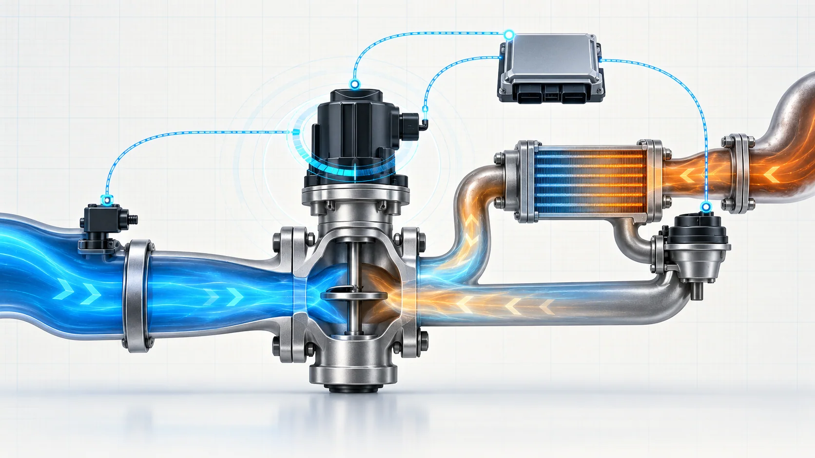
On the verified 2022 source application, the ECM drives the EGR valve with a bidirectional electric motor. An integral position sensor reports valve position through reference, signal, and low-reference paths. This creates a closed-loop position system: the ECM requests movement, the motor moves the valve, and the position signal reports the result.
The gas path adds another layer. Exhaust is routed through a cooler or a cooler-bypass path according to operating conditions, then mixed with intake air. The ECM uses mass-airflow response as part of its evidence that commanded valve movement actually changed EGR flow. The intake-airflow valve, induction path, exhaust path, turbocharger, EGR cooler, bypass valve, and EGR passages can therefore affect the conclusion.
The diagnostic logic asks four separate questions:
- Did the ECM command the EGR motor correctly?
- Did the valve-position signal follow the command plausibly?
- Did the expected airflow response occur?
- Are the supporting intake, exhaust, cooler, and boost paths healthy enough for that response to be meaningful?
Electrical movement does not prove useful gas flow. A clear gas path does not prove that the motor, position sensor, connector, or circuits are healthy.
What the related DTCs tell you
| DTC | Diagnostic category | What it directs you to prove |
|---|---|---|
| P0401 | EGR flow insufficient | Whether commanded EGR activity creates the expected airflow response, and whether restriction, leakage, valve binding, cooler or bypass restriction, intake or exhaust faults, turbocharger conditions, or misleading airflow evidence explain the weak response |
| P0403 | EGR motor-control circuit | Whether the bidirectional motor-control paths, connector, harness, actuator, or controller-side output explain the electrical failure |
| P0404 — branch 01 | Open-position performance | Whether desired and actual valve position agree during commanded movement, after related electrical faults have been excluded |
| P0404 — branch 02 | Alternate open-position performance path | Whether position plausibility and circuit integrity support a mechanical or component conclusion on the applicable procedure branch |
| P0405 | EGR position-sensor circuit low | Whether the reference, signal, low-reference, connector, wiring, integral sensor, or controller-side input is forcing an implausibly low position signal |
The code identifies the evidence path that failed. It does not choose the replacement part.
What the driver or technician may notice
- a malfunction indicator lamp or service-emissions message with little immediate drivability change;
- reduced power or a speed limitation associated with an active emissions-system fault;
- hesitation, roughness, smoke, unstable combustion, or reduced response when EGR flow is incorrect;
- a fault that appears only after the engine is warm and the monitor reaches its enabling conditions;
- several EGR control, position, or flow codes rather than one isolated DTC;
- desired and actual valve position that disagree during a scan-tool command;
- position feedback that is fixed low, fixed high, or implausible before the valve is commanded;
- soot at an EGR joint, heat damage near the harness, or heavy deposits in the valve, cooler, or passages;
- a repeat fault after valve replacement because the gas path, supporting airflow system, wiring, or verification step was not addressed.
These observations are clues, not proof. Preserve the complete vehicle scan, code status, freeze-frame or failure-record data, event data, relevant airflow and EGR parameters, and recent repair history before clearing anything.
Common failure categories
Restricted EGR path, cooler, or deposits
Soot and deposits can restrict the valve, passages, cooler, or bypass path. The position sensor may show that the valve moved while the airflow response remains too small. Deposits can also make the mechanism bind or prevent it from reaching the requested position.
Do not assume every P0401 is a dirty valve. Prove which section is restricted and use the cleaning or replacement method approved for the exact truck. Excessive deposit buildup should also trigger a review of the conditions that created it.
Leakage in the intake or exhaust path
Leaks at EGR joints, cooler connections, tubes, intake plumbing, or exhaust components can change the relationship between command and measured response. Escaping exhaust may leave soot and can damage nearby wiring or heat-sensitive parts.
Inspect only after the system has cooled. Visible soot is useful evidence, but the current service procedure controls the actual leak test and repair decision.
Valve motor or mechanical movement faults
The motor, internal mechanism, valve shaft, or seat can bind, wear, overheat, or fail. A scan-tool command proves only that the ECM requested movement. Position feedback can prove reported movement, but neither one alone proves that the gas path delivered the required flow.
Compare desired position, actual position, motor-control integrity, and airflow response instead of judging the valve from sound or one data snapshot.
Position-sensor and circuit faults
The integral position sensor depends on a stable reference, signal path, low reference, connector fit, and terminal integrity. A short to ground, short to voltage, open or high resistance, corrosion, water intrusion, heat damage, chafing, backed-out terminal, or internal sensor fault can create false position evidence.
Circuit faults take priority over performance conclusions. If the ECM cannot trust position feedback or control the motor, do not use the resulting airflow behavior to condemn the gas path.
Supporting airflow, induction, exhaust, or boost faults
The EGR monitor does not operate in isolation. A restricted air cleaner, biased or contaminated airflow sensor, leaking or restricted induction path, exhaust restriction or leak, intake-airflow valve problem, or turbocharger condition can distort the response that the ECM expects when EGR is commanded.
P0401 therefore requires a system view. Replacing the EGR valve without proving the supporting paths can leave the original fault untouched.
Calibration, setup, and controller-side conditions
Software applicability, learned positions, and required post-repair routines can affect how the ECM judges EGR operation. Controller replacement belongs at the end of the diagnostic tree after the motor, position sensor, circuits, terminals, mechanical movement, supporting paths, calibration, and required setup have been proven.
A practical system-first diagnostic strategy
1. Confirm the exact configuration and preserve evidence
Verify the VIN, model year, engine, emissions equipment, calibration, and installed EGR hardware. Save all module codes, status, freeze-frame or failure records, event data, EGR desired and actual position, mass-airflow data, engine temperature, load, speed, and recent repair history before clearing codes.
2. Establish fault priority
Separate circuit faults from performance faults. Diagnose active reference, signal, low-reference, or motor-control DTCs before trusting a P0401 or P0404 conclusion. A flow test is not authoritative when the valve command or position feedback is unreliable.
3. Inspect the cold system
Allow the exhaust and EGR hardware to cool. Inspect connectors, locks, terminals, harness routing, heat protection, cooler and bypass connections, tubes, intake plumbing, exhaust joints, and recently disturbed areas. Look for soot, deposits, corrosion, water intrusion, chafing, heat damage, loose retention, or previous test damage.
4. Compare command, position, and airflow response
Use a capable scan tool and the applicable procedure. Ask three distinct questions:
- Did the ECM request valve movement?
- Did actual position follow desired position plausibly?
- Did mass airflow and other engine evidence respond as expected?
Command without position response points toward motor control, wiring, terminals, binding, feedback, or the assembly. Position response without the expected airflow change points toward restriction, leakage, supporting-airflow faults, or false position evidence.
5. Prove circuits without creating new faults
Use the exact connector views, breakout method, meter loading, fused jumper, shutdown timing, and controller precautions specified for the vehicle. Do not borrow pin numbers, wire colors, or thresholds from another year or procedure branch. Avoid probing sealed or controller terminals in a way that spreads, corrodes, or shorts them.
An unloaded voltage reading does not prove that a motor-control circuit can carry current. A forced signal response may prove part of the input path without proving the valve mechanism or gas flow.
6. Isolate restriction, leakage, and supporting-system faults
After electrical control and position feedback are credible, inspect the valve, passages, cooler, bypass path, intake system, exhaust system, airflow sensing, intake-airflow valve, and turbocharger according to current service information. Do not force the valve, pressurize the system, or introduce cleaners outside the approved procedure.
7. Choose the repair category after localization
The supported repair may be a connector or harness repair, leak repair, cooler or passage service, approved cleaning, valve-assembly replacement, supporting-airflow repair, calibration update, required setup, or—only after complete isolation—controller repair or replacement. Match the repair to the failed section, not to the DTC label.
8. Complete setup and verify the repair
Restore every connector, lock, harness support, heat shield, and gas-path joint. Perform any required setup or learned-position routine. Then reproduce the stored operating region or run the specified verification procedure. Confirm that desired position, actual position, and airflow response agree and that related event data, pending codes, and confirmed codes remain clear.
Clearing the warning lamp is not a completed verification. The fault must run and pass under the applicable conditions before the emissions message or limitation can be considered resolved.
Safety around the diesel EGR system
EGR components carry hot exhaust and may remain hot after shutdown. Allow adequate cooling time, wear suitable eye and hand protection, and keep tools, leads, chemicals, and flammable material away from hot surfaces. Exhaust gas is hazardous; use effective extraction and ventilation whenever the engine must run indoors.
Running tests place the technician near belts, fans, turbocharger and exhaust heat, and potentially moving driveline components. Secure leads and tools, place the transmission in the specified state, apply the parking brake, and follow current service information before commanding an actuator or raising engine speed. Do not open hot coolant connections at the EGR cooler, disturb pressurized systems, or use unapproved cleaners, compressed air, or electrical jumpers.
Final takeaway
The 2020–2025 Chevrolet Silverado 2500 6.6L Diesel EGR system is a layered control problem. The ECM drives the valve motor, the position sensor reports movement, and airflow response shows whether useful exhaust flow occurred through the cooled gas path. P0401, P0403, P0404, and P0405 describe different breaks in that chain: flow response, motor control, position performance, and position-signal integrity.
Begin with exact configuration and stored evidence, resolve electrical faults before performance faults, compare desired position with actual position and airflow response, and inspect the complete EGR, intake, exhaust, cooler, bypass, and boost paths before choosing a repair. The linked STEP guides provide code-specific educational paths; current service information for the exact truck controls specifications, connector details, commands, procedures, and final verification.