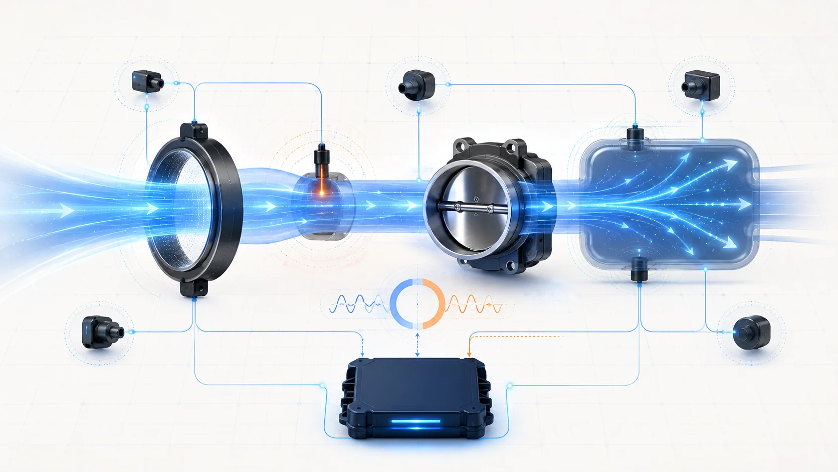
What the airflow and load sensing system does
The airflow and load sensing system gives the powertrain control module (PCM) the evidence it needs to estimate how much air is entering the engine and whether that air agrees with throttle command, pressure, temperature, engine speed, and engine response. The PCM uses this model to coordinate fuel delivery, ignition, electronic throttle control, boost control, emissions monitoring, and protective strategies.
Private service-information targets confirm 2015 and 2025 F-150 4WD 2.7L turbo endpoints, while the linked STEP guides use the 2015-2025 educational grouping. The detailed controller and fuel-control descriptions reviewed for this overview are from the exact 2025 application. Confirm the VIN, engine application, calibration, sensor packaging, connector information, and current service procedure before testing. Exact monitor logic, values, and procedures can differ within the grouped range.
An airflow DTC does not automatically prove that an airflow sensor has failed. The PCM may reject a signal because the circuit is open or shorted, because the sensor is biased or contaminated, because air is leaking or restricted, or because several individually plausible signals do not agree with one another.
The main functional sections
- Air inlet and ducting: The filter, housing, ducts, clamps, seals, and charge-air path must carry air without unintended leaks, collapse, disconnection, or restriction.
- Mass-airflow measurement: The mass air flow (MAF) input represents the amount of air moving through the measured intake path. Depending on the exact application, temperature sensing may share a housing or connector with another air sensor.
- Intake-air temperature: The intake air temperature (IAT) input helps the PCM interpret air density and distinguish a believable operating condition from an electrical fault.
- Throttle command and position: The electronic throttle body meters airflow. The PCM knows what it commanded and monitors the resulting throttle position and engine response.
- Pressure and load evidence: Intake-manifold, charge-air, ambient, and barometric information may contribute to the PCM's load model. Availability and sensor arrangement vary by exact vehicle.
- Engine-speed and combustion response: Engine speed and the resulting torque or combustion behavior help the controller decide whether the air model is credible.
- PCM reference, signal, return, and network paths: Sensor circuits must be electrically sound, and related module data must be available, before the PCM can make a trustworthy comparison.
How the signals work together
The PCM does not diagnose airflow from one number in isolation. It predicts what airflow should look like for the current throttle angle, engine speed, pressure, temperature, and operating state, then compares that prediction with measured evidence. Fuel control and electronic throttle operation depend on the same basic agreement.
The MAF input describes air passing the measurement point. The IAT input adds temperature context because equal volumes of hot and cold air do not represent the same air mass. Throttle position tells the PCM how open the commanded air path is. Pressure and engine-speed information help describe how strongly the engine is drawing or receiving air. When these inputs change together in a believable direction, the model remains credible.
A circuit fault can produce an obviously high or low signal. A performance fault is different: the signal may be electrically present but disagree with the rest of the system. Air entering through an unintended path, a restricted duct, a distorted sensor signal, incorrect sensor data, or an engine condition that changes pumping efficiency can all create that disagreement.
What the related DTCs are telling you
| DTC | Diagnostic category | What it directs you to prove |
|---|---|---|
| P0068 | Airflow or load information does not agree with throttle position | Whether an intake, PCV, vacuum, crankcase-sealing, throttle, sensor, circuit, or supporting-input concern caused the rationality failure |
| P0101 | MAF range/performance | Whether measured airflow is credible for the operating condition and whether air-path, engine, connector, wiring, or sensor evidence explains the mismatch |
| P0102 | MAF circuit low | Whether the low input comes from the air condition, sensor, connector, signal path, shared electrical path, or controller side |
| P0113 | IAT circuit high | Whether the high electrical indication is caused by the sensor, an open or shorted circuit, terminal condition, an intermittent, or controller-side interpretation |
P0101 is not the same diagnosis as P0102. P0101 asks whether the airflow result makes sense; P0102 directs attention to a low electrical input. P0113 focuses on the temperature signal path. P0068 asks whether multiple parts of the air and load model agree. Related circuit codes should normally be understood before treating a rationality code as an independent failure.
What the driver or technician may notice
Possible observations include:
- a malfunction indicator lamp with no obvious drivability complaint;
- rough running, hesitation, stalling, or reduced power;
- inconsistent throttle response or a protective power limitation;
- hard starting or a fueling complaint under some conditions;
- fuel-trim or mixture evidence that changes with engine speed or load;
- a concern that appears after air-filter, intake, charge-air, throttle-body, PCV, engine, or harness work;
- scan data that is fixed, implausible, slow to respond, or inconsistent with other temperature and load inputs;
- companion throttle, pressure, temperature, fuel-control, reference-circuit, or power-supply DTCs.
Symptoms identify the conditions that reproduce the concern; they do not identify the failed component.
Safety before airflow testing
Keep hands, tools, loose clothing, shop towels, smoke-test hoses, and test leads clear of belts, fans, the throttle plate, turbocharger inlet plumbing, and other moving or ingesting parts whenever the engine can run. Never leave loose objects in an open intake. Reassemble the air path before operating the engine unless the exact procedure requires a controlled test configuration.
Allow hot engine, exhaust, turbocharger, and charge-air components to cool before working nearby. Use eye protection and follow the equipment manufacturer's instructions for smoke or pressure testing. Do not exceed the pressure allowed by the exact service procedure, and do not introduce shop air into the intake without the specified regulator and connection method.
Use terminal-safe probes and the exact wiring diagram. Do not pierce insulation unnecessarily, force probes into terminals, apply battery voltage to sensor or PCM circuits, or substitute a generic jumper for a directed test.
Common failure categories
1. Intake or charge-air leak
A loose clamp, damaged seal, split hose, disconnected fitting, or cracked duct can make the air reaching the engine differ from the air the PCM expects. The effect depends on where the leak is located and the operating condition. Inspect the complete accessible air path rather than concentrating only on the named sensor.
2. PCV, vacuum, or crankcase-sealing fault
Air entering through the crankcase ventilation or another vacuum path can disturb the relationship among throttle position, airflow, pressure, and engine response. Check hoses, valves, caps, seals, and recent service areas using the exact system layout. P0068 may be evidence of unintended air even when the electronic throttle body is responding correctly.
3. Restriction or disturbed airflow
A restricted filter, collapsed duct, obstructed inlet, damaged airbox, or improperly installed component can reduce or distort flow through the measurement area. Contamination at a sensing element can also bias the result. Inspect first; clean or replace only when the approved service method and evidence support it.
4. Sensor fault or incorrect temperature evidence
A MAF or IAT sensing element can be biased, intermittent, slow, open, or shorted. Temperature data should make physical sense for the vehicle's stabilized condition, and airflow should change logically with operating state. Use comparison and response testing from the exact procedure instead of applying a universal number.
5. Connector, reference, signal, or return fault
Corrosion, water, oil intrusion, terminal spread, poor retention, chafing, heat damage, or a shared reference/return problem can change one or several inputs. Review companion codes and test the circuit under the conditions that expose the fault. A connector that looks clean can still have poor terminal contact.
6. Throttle, pressure, or supporting-input disagreement
The MAF signal can be reasonable by itself while another input causes the calculated relationship to fail. Compare commanded and actual throttle behavior, pressure evidence, temperature inputs, engine speed, and relevant load information before replacing the MAF sensor.
7. Engine mechanical or exhaust condition
An engine sealing, valve-timing, combustion, or exhaust restriction concern can change how much air the engine actually moves. Expand into mechanical testing only when scan evidence, inspection, companion DTCs, or the directed procedure supports that branch.
8. PCM or calibration concern
Controller replacement belongs at the end of the diagnostic path. Prove power, ground, reference, signal, return, connector integrity, sensor response, air-path condition, and applicable software or configuration requirements first.
A practical diagnostic workflow
1. Preserve the evidence
Record all module DTCs, status, freeze-frame or snapshot data, engine temperature, engine speed, load, throttle state, and the conditions that produced the complaint. Note recent intake, filter, turbocharger, PCV, throttle, engine, battery, or wiring work.
2. Establish diagnostic priority
Handle power, ground, reference-circuit, communication, and direct sensor-circuit faults before assuming a performance or rationality code is independent. A low MAF circuit code or high IAT circuit code can explain why a later airflow comparison fails.
3. Inspect the entire air path
Verify the filter and housing are correct and seated. Inspect ducts, clamps, seals, vacuum and PCV connections, charge-air joints, accessible wiring, and connectors. Look for rubbing, heat damage, contamination, loose service connections, or a fault that changes with engine movement.
4. Check key-on and stabilized plausibility
With the exact service procedure, compare available temperature and pressure inputs under a known stable condition. Look for one value that is fixed or unreasonable relative to the others. Do not assume every model year exposes the same sensors or scan-data names.
5. Observe response rather than one snapshot
Watch airflow, temperature, throttle, pressure, engine-speed, and fuel-control evidence during a safe, repeatable operating change. A signal should respond smoothly and in a physically believable direction. A sudden dropout during a controlled harness movement supports an intermittent circuit concern; a consistent mismatch may point toward air-path, sensor-bias, or mechanical investigation.
6. Prove the circuit correctly
Follow the exact wiring diagram and pinpoint test. Check terminal condition before measurements, isolate the correct circuit, and use the specified loaded voltage, voltage-drop, continuity, or response test. Do not copy connector IDs or thresholds from another year or configuration.
7. Test for leakage or restriction only as directed
Use the approved inspection, smoke, pressure, vacuum, or flow method for the exact section of the air path. Control test pressure and isolate the system as instructed. A leak-test result proves only the area and conditions actually tested.
8. Repair the proven cause and verify
Repair the leak, restriction, terminal, wiring, sensor, or mechanical condition that fails the test. Restore every connector and duct, clear learned data only when the procedure requires it, repeat the relevant self-test or drive condition, and confirm that the signals agree, the symptoms are gone, and no DTC returns.
What not to do
- Do not replace the MAF or IAT sensor from the code name alone.
- Do not treat P0101, P0102, and P0068 as interchangeable faults.
- Do not ignore a direct circuit code while diagnosing a rationality code.
- Do not spray an unapproved cleaner on a sensing element or touch it with tools.
- Do not run the engine with loose objects or unsecured ducting near an open intake.
- Do not pressure-test the intake with unrestricted shop air.
- Do not apply exact pins, voltages, PID names, or test thresholds across the full 2015-2025 range.
- Do not condemn the PCM until the inputs, circuits, air path, and supporting evidence are proven.
The diagnostic principle to remember
Airflow diagnosis is a credibility test. Prove that the air path is intact, each electrical signal is trustworthy, and the measured air agrees with throttle, temperature, pressure, engine speed, and engine response. When those proofs are kept separate, the DTC becomes a useful direction instead of a parts-replacement instruction.