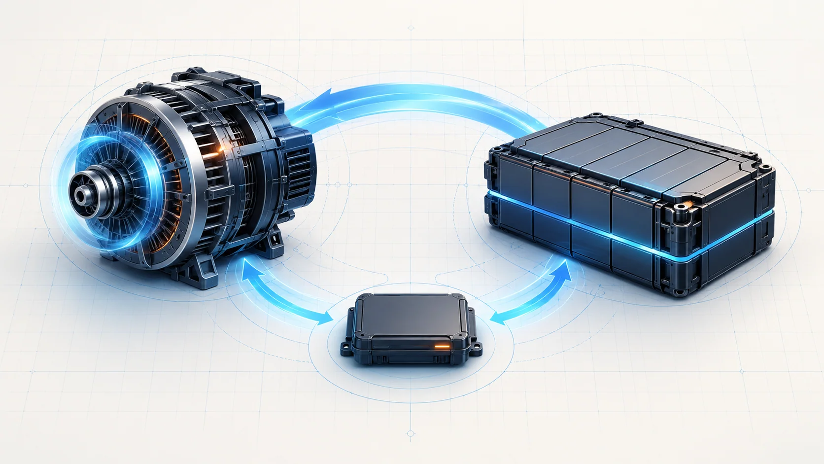
Charging diagnosis is not just an alternator voltage check. The engine-driven alternator, battery, power connections and control inputs must work together. A weak supply, an implausible load signal and a missing communication message are different problems, even when they produce similar complaints.
This overview covers the 2010–2017 Honda Accord 2.4 gas family at a functional level. These are not identical engines or charging architectures. The source examples include a 2010 Accord L4-2.4L with an electrical load detector and a 2017 Accord Sedan L4-2.4L K24W1 with LIN-based alternator and battery-sensor supervision. Do not assume every listed DTC or component is fitted to every year. Identify the actual vehicle, engine, equipment and wiring before using a diagnostic chart. The applicable service information controls exact commands, limits, terminals and repair procedures.
What the system does
The charging system supports electrical consumers while the engine runs and replenishes energy used from the battery. Reliable diagnosis separates energy production and delivery from the information used to manage them. An alternator may be capable of producing power while a control message is missing; conversely, a communication circuit can be intact while a power connection cannot carry the required current.
The battery is also part of the diagnosis, not a passive witness. Its condition and connection quality affect starting, electrical stability and how charging results should be interpreted. A single reading taken without knowing operating conditions is not a complete charging-system assessment.
Two source configurations, not one universal layout
In the 2010 source example, the electrical load detector, or ELD, monitors electrical load and provides a signal to the ECM/PCM. The P1298 ELD circuit guide belongs to that signal-diagnosis category. A high ELD signal does not, by itself, establish excessive alternator output or prove that the battery is overcharging.
The 2017 K24W1 example uses communication between the PCM and alternator over a local interconnect network, or LIN. Commands and feedback allow the control system to manage generation according to operating needs. The target is not one fixed voltage for every load, engine speed and battery condition. P16E2, PGM-FI to ACG LIN communication error, concerns this communication path rather than proving a failed alternator.
The 2017 source also describes a battery sensor that measures battery current, voltage and temperature. Its LIN connection is to the gauge control module; information reaches the PCM through CAN. This is not the same direct LIN path as the alternator-to-PCM connection. P16E3, battery-sensor LIN communication error, therefore needs the battery-sensor communication chart, not an assumed alternator LIN test.
Failure categories and what the codes actually tell you
- Load-information circuit: P1298 directs attention to the ELD signal and its electrical support on a vehicle that uses that arrangement. A signal fault is not automatically a failed detector; feeds, grounds, terminals and wiring remain candidates.
- Battery-sensor internal-failure category: the P154A battery-sensor guide is separate from a LIN communication fault. The 2017 troubleshooting source still checks the sensor supply path before directing component replacement. The code name is not permission to skip those checks.
- Generation and power-path performance: P16BB, alternator B-terminal circuit low voltage, concerns monitored charging behavior under defined command and operating conditions. It is not interchangeable with a lost LIN message. Battery condition, power connections, alternator operation and the applicable circuit checks must be considered together.
- Communication integrity: P16E2 and P16E3 identify different paths. Loss of a message may involve supply, ground, terminal contact, the communication conductor or the participating device. Diagnose the named path before condemning either endpoint.
These categories are more useful than a list of replacement parts. Several codes can coexist, and low system supply can complicate other observations. Record all codes and their status before deciding which concern is primary.
Symptoms and useful evidence
A charging complaint may include a warning, difficult starting, a discharged battery or intermittent electrical behavior. Some faults may leave only stored diagnostic evidence, and the vehicle may appear normal when inspected. Neither normal operation now nor the absence of a check-engine lamp proves that every charging monitor has passed.
Save available freeze-frame data and onboard snapshots before clearing anything. Record whether the fault is current, pending, confirmed or intermittent, along with engine state, electrical loads and relevant charging or sensor data supported by the scan tool. Compare command, feedback and physical measurements only under conditions supported by the vehicle's procedure. A voltage measurement does not prove communication quality, and a plausible scan value does not prove that a high-current cable can carry load.
A practical diagnostic strategy
- Establish applicability and the complaint. Confirm the installed charging arrangement and use the exact year/engine chart. Keep the early ELD example separate from the later LIN examples; do not invent a combined wiring diagram.
- Preserve evidence and assess the basic supply. Review the battery condition, terminal security and visible power/ground connections using the applicable service checks. Inspect for damaged wiring, corrosion or repairs that could affect the concern. Do not disturb connectors before saving useful fault evidence.
- Reproduce the fault appropriately. Follow the chart's operating conditions and distinguish an active failure from an intermittent one. If it does not return, investigate connection quality and the recorded circumstances rather than declaring a component failed.
- Separate the paths. For ELD or sensor concerns, establish the required feed and ground before interpreting signal behavior. For a LIN concern, use the correct communication route and isolation sequence. For a generation complaint, evaluate output and delivery under the prescribed conditions rather than applying a universal idle-voltage rule.
- Escalate only after the basic checks. Component substitution, software checks and module-related procedures belong only where the applicable diagnostic chart requires them. An arbitrary used module is not a shortcut around proving the circuit.
The linked guides help locate the relevant diagnostic category. Their broad family URLs do not make their exact tests valid for every configuration in the title range. Stop and obtain the matching service procedure whenever connector identity, circuit topology or test conditions differ.
Repair categories and verification
Repairs may involve restoring a feed or ground, correcting terminal fit, repairing a damaged conductor, servicing a power connection or replacing a component shown faulty by the applicable tests. A battery concern and a charging-control concern may need separate confirmation. Do not replace the alternator merely because a charging-related code is present, or replace the battery sensor merely because its name appears in a code.
After repair, restore all connections and carry out only the required resets, initialization or learning procedures for that vehicle. Recheck pending and confirmed codes and relevant charging data under the prescribed verification conditions. If the original fault returns, return to the chart; if different faults remain, diagnose them separately. A cleared memory or one successful restart is not complete verification.
Safety before probing
Battery and alternator power circuits can deliver damaging current. Avoid bridging a live power terminal to ground, use correctly rated test equipment and follow the specified isolation procedure before disconnecting or servicing components. Never disconnect the battery with the engine running as an alternator test. Keep leads, clothing and hands clear of rotating belts, pulleys and hot components. Do not apply battery power to a LIN or sensor signal wire. Resistance and continuity checks require the circuit state specified by the service procedure, not a live-circuit guess.
Start with the vehicle's actual architecture, then separate supply, sensing, communication and generation. That keeps a charging-system code from becoming an unsupported parts decision.