What this code means
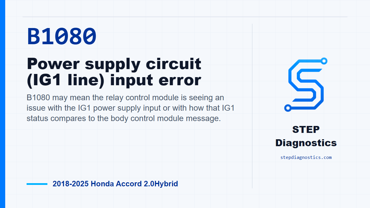
B1080 may mean the relay control module is seeing an issue with the IG1 power supply input or with how that IG1 status compares to the body control module message.
What the vehicle may do
- The vehicle may show body electrical symptoms or ignition-on recognition concerns.
- Warning messages may be present, or the code may appear during network/body electrical diagnosis.
- Symptoms can vary depending on whether the issue is in the IG1 feed, wiring, connector condition, or module-side logic.
Possible fault areas
- Possible IG1 power supply circuit concern
- Possible connector, terminal, or wiring issue
- Possible mismatch between direct IG1 input and B-CAN IG1 status
- Possible body control module, relay control module, or MICU-related logic concern
Diagnostic path
Opening context
For this Accord Hybrid, B1080 is an IG1 power supply circuit input error in the relay control module and MICU area. In plain terms, the relay control module is seeing a mismatch between the direct IG1 input and the IG1 status message coming from the body control module over B-CAN long enough to set the code. The vehicle may have body electrical complaints, ignition-on recognition issues, or warning messages, but it can also be a targeted circuit fault without a big drivability symptom. The possible fault areas are the IG1 feed, the related connector and terminal condition, the body control module side of the signal, and the relay control module or MICU side of the networked logic.
Set up the test correctly
Before getting into pin checks, start with the basic system checks. If multiple body or network codes are present, handle the B-CAN diagnosis path first so you do not chase B1080 out of order. For this code’s confirmation, turn the vehicle to ON mode, then wait for at least 6 seconds. That gives the module time to compare the IG1 input against the IG1 message it is receiving.
Check the IG1_METER circuit
Next, inspect the IG1_METER circuit at body control module connector A, the 66P connector. Test at the female terminals with the connector connected and IG Mode ON. The normal condition for this circuit type is 12 V battery voltage. This is the key split in the diagnostic path: either the IG1_METER circuit is not delivering the expected power, or the circuit checks good and the fault points back toward the body control module logic side.
Use the result to choose the path
If the IG1_METER circuit inspection is abnormal, treat it as a circuit problem. If the power supply inspection in that table is abnormal, the next move is the additional power supply inspection to locate the failure. Do not skip that and do not guess at a module call. Pause there, complete the power-supply diagnostic path, and then come back to the B1080 decision. If the IG1_METER circuit inspection is normal, the diagnostic result is a problem with the body control module.
Takeaway
The clean way through B1080 is to prove the IG1_METER feed first. An abnormal reading keeps you in circuit and power-supply diagnosis. A normal reading points the decision toward the body control module. For more diagnostic training, visit stepdiagnostics.com.
Final check
For B1080, prove the IG1_METER circuit condition first, then follow the result instead of jumping straight to a module decision.
For more guided automotive diagnostics, visit STEP Diagnostics.