What this code means
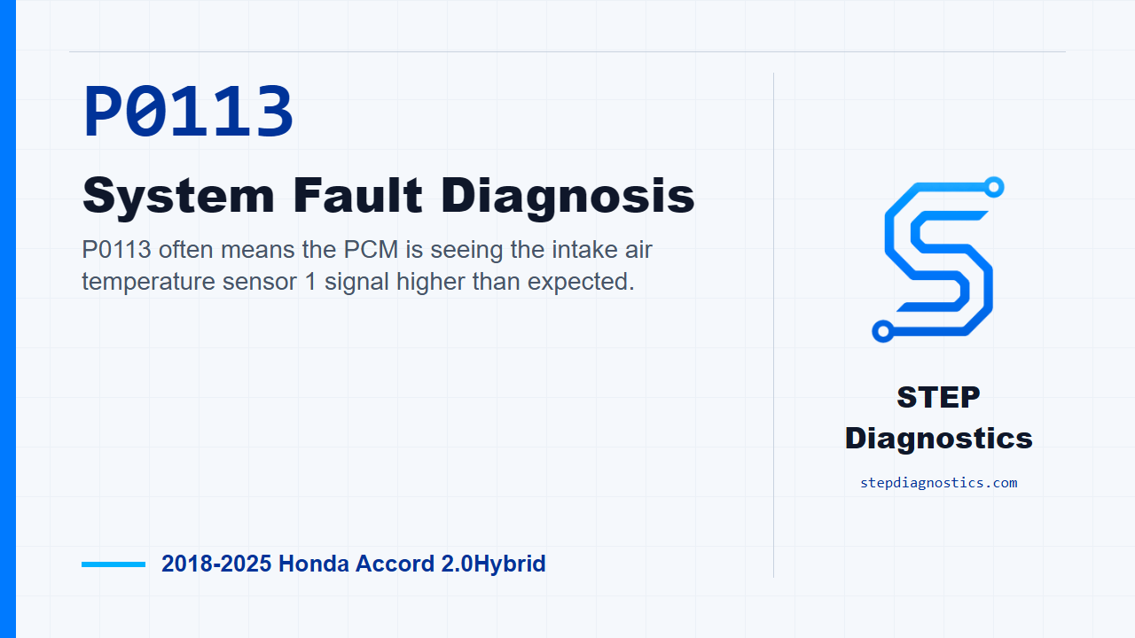
P0113 often means the PCM is seeing the intake air temperature sensor 1 signal higher than expected.
What the vehicle may do
- The vehicle may have drivability changes.
- Fuel control can be affected.
- The code may set when the PCM interprets the IAT 1 signal as too high.
Possible fault areas
- Possible fault areas can include the MAF and IAT sensor 1 assembly.
- Possible fault areas can include the IAT signal circuit and the sensor ground side.
- Connector condition or related wiring may be involved.
- The PCM may be considered only after the related checks are normal.
Diagnostic path
Open and frame the code
On this Accord Hybrid, P0113 is for the intake air temperature sensor 1 circuit reading high voltage at the PCM. In plain language, the PCM is seeing the IAT 1 signal higher than it expects. The vehicle may have drivability changes, fuel control may be affected, and the fault area can be the sensor assembly, the IAT signal circuit, the sensor ground side, related connector issues, or, after the other checks pass, the PCM. Start with the basic system checks, then follow a structured diagnostic approach so you do not jump past the circuit fault that can set this code.
Duplicate the failure
First, confirm the fault. Turn the vehicle to the ON mode and look at the HDS data for IAT Sensor 1 Voltage. If that value is more than 4.92 V, the failure is duplicated. That is the key monitor clue here: the PCM stores this code when the IAT sensor 1 output voltage is higher than the specified value.
Simulate the IAT circuit response
Next, move into the IAT sensor 1 inspection. There is no direct standalone test for the component itself, so the diagnosis is done through the related parts of the circuit. With the vehicle set up for the test, disconnect the MAF sensor and IAT sensor 1 connector, the 4-pin connector. Then jump terminals No. 2 and No. 4 with a jumper wire. Turn the vehicle to the ON mode again and check IAT Sensor 1 Voltage on the HDS. A normal response is less than 4.92 V. If the response is normal during this check, the fault points to the MAF sensor and IAT sensor 1 assembly. If the response is not normal, keep going because the problem is in another related part of the circuit.
Check the IAT1 and SG2 circuits for opens
If the sensor simulation does not bring the voltage into the normal range, check the IAT1 and SG2 wiring for an open. Before disconnecting the PCM connector, jump the SCS line with the HDS and wait more than 1 minute. Then disconnect the MAF sensor and IAT sensor 1 4-pin connector, and disconnect PCM connector B, the 101-pin connector. Perform the open-wire checks for the IAT1 side and the SG2 side. In both checks, the normal result is less than 1 Ω with the ignition mode OFF. If either check is abnormal, the problem is in the circuit.
Do not guess on unclear terminal details
At this point, terminal location matters. If the connector face information or measurement connection details are not clear, pause and recheck the earlier diagnostic path before testing. Do not guess at terminal positions on the PCM or the MAF and IAT connector.
PCM conclusion only after the other checks pass
If the IAT sensor 1 inspection is normal, and the open-wire inspections are normal, then the remaining diagnostic conclusion is a problem with the PCM. That is not the first stop in this routine. It only comes after the sensor response and the IAT1 and SG2 circuit checks have been worked through in order.
Verify and close
After the fault is corrected, verify the repair and confirm P0113 stays gone under the same kind of conditions that duplicated it. The takeaway is simple: prove the high IAT voltage first, simulate the sensor circuit response, check IAT1 and SG2 for opens, and only then consider the PCM. For more diagnostic training, visit stepdiagnostics.com.
Final check
Confirm the high-voltage condition, test the circuit response, check for opens in IAT1 and SG2, and avoid jumping to a PCM conclusion too early.
For more guided automotive diagnostics, visit STEP Diagnostics.