Applicability basis: Exact vehicle records confirm 2.0-liter Honda Accord Hybrid applications at the 2018 and 2025 endpoints used by STEP Diagnostics. Detailed network and DTC evidence for this overview was verified on a 2025 Accord Sedan Hybrid with the LFC5 engine. Installed modules, network branches, gateway functions, connector locations, wire colors, scan-tool menus, and test steps can vary by year, trim, market, and equipment. Current service information for the exact vehicle controls those details.
What the vehicle network does
The hybrid Accord depends on control units sharing information. The powertrain control module, integrated control module, CAN gateway, gauge control module, vehicle stability assist control unit, electric power steering, battery-related controllers, restraint systems, driver-assistance equipment, and body controllers cannot perform every function from their own sensors alone.
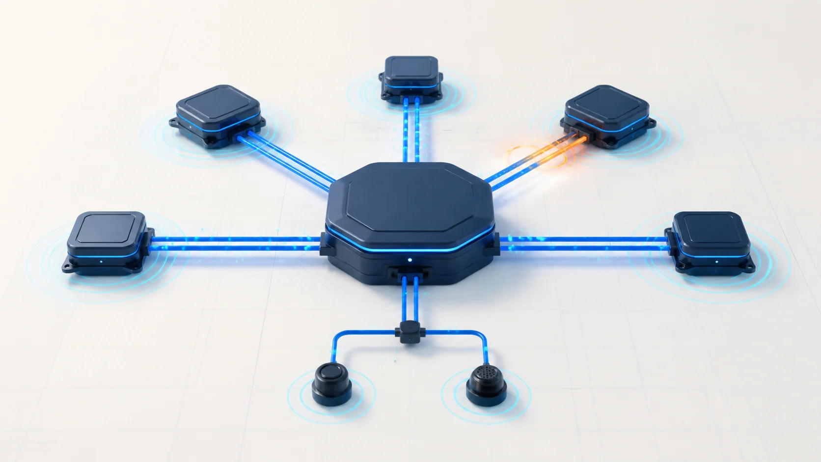
Serial networks let those modules exchange operating state, requests, warnings, and diagnostic information without a separate point-to-point wire for every signal. One module may calculate a value, another may use it for control, the gauge system may display the result, and a scan tool may retrieve DTCs and data from several systems through the diagnostic connection.
The verified 2025 service information describes several communication layers:
- F-CAN: High-speed controller-area-network communication used by powertrain and chassis-related systems.
- B-CAN: Body-network communication used by body-electrical and convenience functions.
- LIN: A lower-speed, single-master communication path used for selected local devices, including the battery-sensor relationship represented by U01B0.
- Gateway functions: Communication domains exchange selected information through gateway logic rather than behaving as one undivided wire pair.
This does not mean every 2018-2025 Accord Hybrid has an identical module list or topology. Identify the exact vehicle and use its current network diagram before deciding which branch, gateway, or controller should be present.
How normal communication works
1. Each module must power up and join its network
A module needs correct power, ground, wake-up conditions, internal operation, and network connectivity before it can communicate. If it never powers up, other modules can report that it is missing even when the communication wiring itself is intact.
This is why a lost-communication code is not automatic proof of a failed network or failed named module. The named module may be unpowered, asleep, disconnected, isolated by a local circuit fault, or unable to communicate because a larger network problem exists.
2. Modules exchange identified messages
On a CAN network, multiple controllers share a communication path and transmit identified messages. Receiving modules monitor the information they require. If an expected message stops arriving under the applicable conditions, a reporting module may store a lost-communication DTC.
For a lost-communication DTC, the module storing the code is the reporter. The module or data source that the applicable procedure says it stopped hearing is the missing or affected communicator. Bus-off codes instead describe the reporting controller's network state, and a code title may identify a reporter, network channel, or module relationship rather than one missing module. The title alone is not a component verdict. Use the code owner and exact procedure to identify the relationship, then determine whether the cause is local power, ground, connector, network circuit, gateway behavior, software state, or an internal controller fault.
3. A bus-off fault is different from one missing message
A controller can stop participating when it detects repeated communication errors. A bus-off code such as U0029 or U0038 points toward a network-level communication failure from a particular module's perspective. The cause may be a shorted or open communication path, a poor terminal, a damaged branch, an unpowered connected module, or a controller/transceiver that is disturbing the bus.
The diagnostic pattern matters. One module missing while most of the network remains accessible suggests a local branch or module-side problem. Several modules disappearing together, or multiple bus-off reports on the same domain, suggests a shared circuit, power, ground, splice, gateway, or connected-unit problem.
4. LIN uses a local master-and-device relationship
LIN is not diagnosed as if it were simply another high-speed CAN pair. A master controller manages communication with one or more local devices over a simpler bus. U01B0 therefore directs attention to the integrated control module, battery sensor, their power and grounds, the local LIN path, and related electrical conditions rather than to the entire F-CAN network. Another installed device can share that exact LIN branch and load or short the path; the verified 2025 procedure includes isolation of the shutter grille when equipped. Identify every device on the applicable branch and follow the directed isolation sequence before blaming the battery sensor or master controller.
5. The scan tool builds a communication map
A complete vehicle scan shows which modules answer, which modules do not, which module stored each U-code, and whether several reporters identify the same missing controller. That network map is often more useful than one code title.
Scan-tool communication with one module does not prove that all networks are healthy. Conversely, failure to communicate with the vehicle can involve the diagnostic connection, basic power or ground, a gateway relationship, or a network fault. Preserve the original scan pattern before clearing codes or disconnecting modules.
Main functional parts
- Control modules and transceivers: Each module contains logic and a communication interface, but still depends on ordinary electrical power and ground.
- CAN communication circuits and branches: Opens, shorts, terminal damage, corrosion, water intrusion, harness chafe, or a failed connected device can affect one branch or a larger shared network.
- Gateway and integrated-control functions: These pass selected messages between communication domains and can be the reporting point for several network DTCs.
- LIN master, local device, and single communication path: A local LIN fault requires checking the exact master-device relationship rather than applying a generic CAN test.
- Diagnostic connector and scan tool: The diagnostic path provides module identification, DTCs, status, and directed test functions when the relevant networks and gateway path are operating.
- Low-voltage electrical system: Battery condition, terminals, grounds, fuses, wake-up feeds, and voltage stability affect every module's ability to stay online.
- Hybrid high-voltage system: High-voltage components are a separate safety boundary. A communication complaint does not authorize probing, disconnecting, or opening high-voltage components.
What the related DTCs are telling you
| DTC | Communication category | What it directs you to prove |
|---|---|---|
| U0029 | F-CAN communication-line or bus-off behavior | Which controller stored the code, which network channel is affected on the exact vehicle, whether related network codes are primary, and whether a shared circuit, connected unit, power/ground condition, or controller explains the bus-off state |
| U0038 | Bus-off reported by the integrated control module | Whether the fault is current, which expected units remain accessible, and whether the relevant network path or a connected controller is disrupting communication |
| U0100 | A reporting module lost communication with the PCM | Whether the PCM is actually offline, whether it has correct power and grounds, and whether broader CAN or gateway faults explain the missing messages |
| U0122 | A reporting module lost communication with the VSA control unit | Whether the VSA unit communicates, whether related braking/network codes are primary, and whether local power, ground, connectors, or the relevant communication path explain the loss |
| U0155 | A reporting module lost communication with the gauge control module | Which module stored U0155, whether the gauge module remains accessible, and whether its local electrical conditions, network branch, gateway relationship, or internal operation explains the missing communication |
| U01B0 | Local LIN communication error involving the battery sensor | Whether the integrated control module and battery sensor are powered and connected correctly, whether another equipped device sharing the exact LIN branch is loading the path, whether the LIN circuit is intact, and whether related low-voltage or sensor faults must be resolved first |
The public titles reflect the perspective of particular STEP guides and may not match every module-specific procedure available for every year. Read the code in the module that stored it and use the exact service procedure for that module and configuration.
What the driver or technician may notice
Possible observations include:
- several warning indicators or messages appearing together;
- hybrid, powertrain, brake, stability-control, steering, gauge, driver-assistance, or body functions becoming unavailable, depending on the missing modules;
- a scan tool that communicates with some controllers but not others;
- no scan-tool communication with the vehicle;
- several modules storing codes that identify the same missing controller;
- intermittent warnings after a weak battery, jump-start, collision repair, connector disturbance, water intrusion, or harness movement;
- a stored U-code with no current symptom after communication returns.
These observations are patterns, not component verdicts. Low voltage, an open fuse, a poor ground, an unplugged module, a wake-up problem, or one primary network fault can create many secondary codes.
Safety comes first
This Accord is a hybrid vehicle. Network diagnosis can place the technician near high-voltage components and can involve braking, steering, restraint, and automatic engine-start behavior.
Treat orange high-voltage cables, the service plug, inverter, motor circuits, and high-voltage battery as energized unless the applicable Honda disable procedure has been completed and verified. Only trained personnel with the required protective equipment should perform high-voltage work. A U-code is not authorization to disconnect a high-voltage connector or probe an energized circuit.
Follow exact SRS precautions before disconnecting restraint-system components. Do not measure resistance or apply power to airbag or pretensioner circuits unless the current procedure explicitly directs it. Support the vehicle correctly if a test requires wheel movement, keep tools and leads clear of rotating parts, and do not drive while watching a scan tool.
Use the specified battery-support and module-disconnection procedure. Unstable low-voltage power can reset modules, create misleading U-codes, interrupt programming, or damage a controller.
Common failure categories
One module has lost power, ground, or wake-up input
Other modules can report a missing controller because its fuse, feed, ground, connector, or wake-up condition is wrong. Prove the specified electrical basics before condemning the communication bus or replacing the module.
A local branch or terminal is open or intermittent
A backed-out terminal, corrosion, connector damage, harness chafe, poor splice, or water intrusion can isolate one module while the rest of the network continues to work. Static continuity alone may not expose poor terminal fit or an intermittent connection.
A shared CAN path is electrically disturbed
A short between communication circuits, short to power or ground, damaged twisted pair, failed transceiver, or connected controller can disrupt several modules. Use the accessible/inaccessible module pattern and the exact network diagram to decide which portion is shared.
Low-voltage instability creates secondary communication codes
A discharged battery, loose terminal, charging problem, or voltage drop during starting can make modules reset or wake at different times. Record voltage history and preserve the original DTC pattern before treating every stored U-code as a separate repair.
A gateway, software, setup, or internal controller condition remains
When power, grounds, connectors, and communication paths pass, the exact procedure may lead to software, initialization, programming, gateway, or controller checks. Those are conclusions after the supporting tests, not first steps.
The fault is intermittent
Heat, vibration, moisture, harness position, connector tension, or a brief voltage event can interrupt communication and then disappear. Preserve snapshot information and the complete module list. A history code that does not reset is evidence to investigate, not permission to install a module.
A practical system-first diagnostic strategy
Step 1: Confirm the exact vehicle and equipment
Verify model year, engine and hybrid configuration, trim, installed options, recent repairs, collision work, module replacement, programming history, and battery events. Obtain the exact network diagram and DTC procedure. Do not expect an optional controller to appear on a vehicle that was not built with it.
Step 2: Preserve the complete network evidence
Before clearing codes, perform a full scan. Record every responding module, every nonresponding module, the owner of each code, current/history status, available snapshot data, warning indicators, and low-voltage system condition.
Step 3: Group codes by reporter, missing module, and network
Several reporters naming one missing module point toward that module or its local electrical conditions. Several missing modules on one domain suggest a shared path, power, ground, splice, gateway, or connected-unit problem. A bus-off code deserves priority over downstream lost-message codes when the exact procedure directs that order.
Step 4: Decide whether the named module is online
Try to communicate with the named controller and compare its own DTCs with the reporter's evidence. If it is offline, verify that it should be installed, then test its specified power, grounds, connector engagement, and wake-up conditions. If it is online, look for intermittent, gateway, message, or reporter-side causes.
Step 5: Separate CAN, diagnostic-path, and LIN problems
Do not apply one generic test to every U-code. A no-communication complaint may involve the diagnostic connection or gateway. A bus-off fault may involve a shared CAN path. U01B0 involves a local LIN relationship. Choose the exact path from the module and code owner.
Step 6: Inspect before disconnecting
Inspect accessible connectors, grounds, harness retainers, chafe points, moisture paths, collision areas, and recent service locations. Document connector position and the original scan pattern. Disconnecting many modules at once can erase evidence and create new codes.
Step 7: Perform the directed electrical tests
Use the exact wiring diagram, vehicle state, breakout method, meter or scope, and isolation sequence. The procedure may require continuity, short, terminal, signal, power/ground, connected-unit, or substitution checks. Do not borrow connector pins, resistance values, or waveforms from another year.
Step 8: Make a controller decision only after the supporting paths pass
If electrical, network, related-code, software, and setup checks all pass, follow the directed replacement or substitution decision. Hybrid and security-related controllers can require programming, initialization, calibration, or other setup; they are not casual swap parts.
Step 9: Verify the complete repair
Reconnect and secure every disturbed connector, ground, shield, and harness retainer. Restore any high-voltage, restraint, steering, stability-control, powertrain, or body-system setup required by current service information. Clear codes when directed, repeat the complete network scan, and confirm that every expected module communicates and the original fault does not return.
Verify the affected function and warning indicators under the conditions that originally produced the complaint. One successful communication attempt after a battery cycle is not enough to close an intermittent network repair.
Final takeaway
Network diagnosis on the 2018-2025 Honda Accord 2.0 Hybrid starts with a communication map, not a parts list. Separate the reporting module from the module it says is missing, distinguish one offline controller from a shared bus-off condition, and keep local LIN faults separate from CAN-network faults.
Then prove the basics in order: exact application and equipment, low-voltage condition, module power and grounds, connector integrity, the correct network branch or gateway path, and only then software or controller function. The linked STEP guides organize the fault categories; current Honda service information for the exact Accord controls safety steps, topology, connector references, electrical limits, scan-tool functions, programming, and final verification.