What this system does
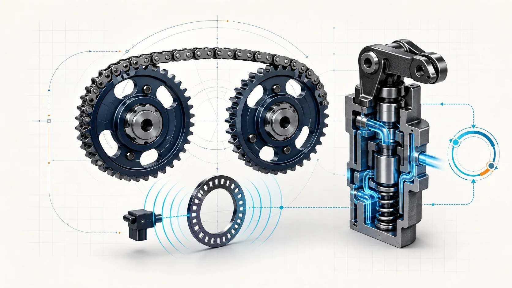
The 1.8-liter Civic combines three related functions that should be diagnosed separately. The cam chain keeps the crankshaft and camshaft in their base mechanical relationship. Crankshaft position (CKP) and camshaft position (CMP) signals tell the powertrain control module (PCM) where the engine is in its cycle. The intake-side VTEC mechanism uses engine oil pressure to select the intended rocker-arm and cam-lobe operation for the current driving condition.
These functions interact, but one code does not prove that every layer has failed. An intermittent CKP or CMP code points first toward signal integrity. A rocker-arm oil-pressure-switch code evaluates feedback from the hydraulic VTEC system. A rocker-arm oil-control-solenoid circuit code is primarily an electrical-control problem until testing proves otherwise.
This overview covers 2010-2015 Civic Sedan applications equipped with the gasoline 1.8-liter engine. The detailed operating examples are based on 2015 R18Z1 service information for USA and Canada models. Honda used different VTEC operating details in some markets, so current service information for the exact VIN controls component identification, test commands, limits, and repair procedures.
The main functional sections
- Mechanical timing drive: The crankshaft, cam chain, guides, tensioner, camshaft, and indexed pulse targets establish the base relationship that the PCM expects.
- CKP signal channel: The CKP sensor and its pulse plate provide the PCM with a repeating crankshaft-position and engine-speed reference.
- CMP signal channel: The CMP sensor and camshaft pulse plate let the PCM identify camshaft position relative to the crankshaft reference.
- VTEC oil control: A PCM-controlled rocker-arm oil-control solenoid routes oil pressure through the rocker shaft to the switching mechanism.
- VTEC feedback: The rocker-arm oil-pressure switch reports whether the hydraulic state agrees with the expected control state.
- PCM strategy: The PCM uses operating information to decide when to command the rocker-arm oil-control solenoid. On the exact 2015 CVT example, the documented inputs include engine speed, load, vehicle speed, throttle position, and coolant temperature.
How normal operation fits together
1. The chain establishes base timing
The chain drive synchronizes crankshaft rotation with camshaft rotation. The position sensors do not create that relationship; they report it. If the chain, tensioning hardware, indexed targets, or assembly position is wrong, the signals can remain electrically present while their mechanical relationship is no longer credible.
Mechanical timing service is precision work. Generic timing marks or an overview illustration are not substitutes for the exact engine-positioning, tensioner, fastener, and verification instructions for the vehicle being repaired.
2. CKP and CMP signals establish position
The PCM receives a stream of pulses as the CKP and CMP targets pass their sensors. It needs a stable pattern during cranking and running, not merely voltage at a stationary connector. A poor terminal, damaged wire, heat-related sensor fault, vibration, target damage, or an unstable ground can interrupt that pattern briefly enough to set an intermittent DTC.
Because the event can disappear before the vehicle reaches the bay, saved freeze-frame or on-board snapshot information matters. The stored engine-speed, vehicle-speed, temperature, and load region helps the technician reproduce the condition safely instead of disturbing the harness and erasing the best evidence first.
3. VTEC changes rocker-arm operation hydraulically
On the USA and Canada R18Z1 example, the PCM switches the intake-side VTEC arrangement according to operating conditions. The oil-control solenoid changes the hydraulic path in the rocker shaft, moving a switching piston that either links or separates rocker arms. This determines which cam-lobe behavior operates the applicable intake valve.
The important diagnostic point is that this is both an electrical and a hydraulic system. The PCM must command the solenoid, the circuit and solenoid must respond, oil must reach the switching mechanism, the mechanical parts must move, and the pressure switch must report the expected state. A fault in one layer can resemble a fault in another.
4. Feedback closes the loop
The rocker-arm oil-pressure switch does not identify the cause of a hydraulic-state error by itself. Unexpected feedback can result from the switch or its circuit, incorrect oil level, an oil-control-valve problem, a connector fault, or another condition found by the directed procedure.
Similarly, a high-voltage solenoid-circuit code does not prove that the oil pressure or rocker mechanism is defective. The electrical control path should be proved before hydraulic or mechanical parts are condemned.
What the related DTCs are telling you
| DTC | Diagnostic category | What it directs you to prove |
|---|---|---|
| P0339 | Intermittent CKP signal | Whether the CKP circuit, connector, grounds, sensor, pulse plate, or PCM input explains interrupted crank pulses |
| P0369 | Intermittent CMP signal | Whether the CMP circuit, connector, grounds, sensor, pulse plate, or PCM input explains interrupted cam pulses |
| P2647 | VTEC pressure-switch circuit high | Whether oil level, pressure feedback, the switch circuit, oil-control hardware, connections, or PCM control explains the unexpected state |
| P2649 | VTEC oil-control-solenoid circuit high | Whether the solenoid winding, ground side, control wire, connector, or PCM driver explains the electrical result |
The complete code set determines the order. If P0339 or P0369 is present, establish reliable position signals before making conclusions from timing behavior. If P2647 and P2649 appear together, follow the related-code priority in current service information rather than assuming that a single replacement part will solve both.
What the driver or technician may notice
Possible observations include:
- a malfunction indicator lamp with little or no obvious drivability change;
- extended cranking, intermittent hard starting, uneven running, or a stall when a position signal drops out;
- a concern that appears only at a particular temperature, engine speed, load, road vibration, or harness position;
- reduced or inconsistent performance when the commanded VTEC state is not achieved;
- several position-signal, misfire, oil-control, or pressure-feedback codes that need to be evaluated together;
- abnormal mechanical noise that requires base-engine inspection rather than immediate sensor replacement.
None of these observations proves a failed sensor, chain, solenoid, pressure switch, or PCM. Battery voltage, starting speed, ignition, fuel delivery, oil condition, base-engine condition, and other faults can produce overlapping symptoms.
Common failure categories
Position-signal interruption
Loose terminal tension, corrosion, damaged wiring, heat, vibration, an internally intermittent sensor, ground trouble, or pulse-plate damage can corrupt CKP or CMP pulses. A static resistance or voltage check may pass even though the running waveform is unreliable.
Electrical VTEC control fault
An open circuit, excessive resistance, short, damaged connector, failed solenoid winding, or PCM-driver concern can prevent the oil-control command from reaching the valve. Prove the electrical path with the correct wiring information before judging hydraulic operation.
Hydraulic VTEC fault
Incorrect oil level or faulty oil-control hardware can prevent the switching mechanism from reaching the intended state even when the electrical command is correct. The directed procedure determines whether further hydraulic or mechanical inspection is justified.
Feedback fault
The pressure switch or its wiring can report the wrong state. Diagnosis must distinguish a false electrical report from a real hydraulic state that does not match the command.
Mechanical timing or target fault
Chain wear, tensioner or guide trouble, incorrect assembly, damaged indexing, or pulse-plate damage can change the physical relationship that the sensors report. Mechanical inspection becomes justified when signal, circuit, oil-control, and operating evidence points there; it should not be the first response to every intermittent sensor code.
A practical system-first diagnostic strategy
Step 1: Confirm the application and preserve evidence
Verify the VIN, model year, engine, market, calibration, oil specification, service history, and recent repairs. Save confirmed, pending, and history DTCs with freeze-frame or on-board snapshot data before clearing anything. Note whether the concern followed battery disconnection, sensor work, valve-cover work, oil service, or timing repair.
Step 2: Classify the code set
Separate CKP/CMP signal faults from VTEC solenoid-circuit faults and pressure-feedback faults. Follow Honda's related-code priorities. A direct signal fault can undermine later timing conclusions, while a direct solenoid-circuit fault should not be explained away as an oil-pressure problem without circuit testing.
Step 3: Check oil and basic engine condition
Verify the oil level and inspect oil condition and service history. Do not use an oil change as a universal repair, but do not skip the oil supply on a hydraulically operated valve-control system. Address abnormal mechanical noise, low cranking speed, or other base-engine evidence before relying on scan data alone.
Step 4: Inspect without destroying intermittent evidence
With the engine safely off, inspect accessible CKP, CMP, and rocker-arm-control connectors and harnesses for incomplete engagement, terminal movement, chafing, oil contamination, heat exposure, poor routing, and recent disturbance. Record what you find before unplugging a suspect connector.
Step 5: Reproduce the stored operating region safely
Use the applicable scan data and Honda test functions. If the code is intermittent, compare the stored conditions with current conditions and reproduce them only where it is safe. Watch for a repeatable signal-noise or control result rather than replacing a component because the fault is absent in the bay.
Step 6: Prove circuits and targets
Use the exact wiring diagram and test method to verify the directed supply, ground or return, signal, control, terminal-fit, and short checks. If the electrical path passes, inspect the relevant pulse plate or target when the procedure directs it. Do not back-probe, jumper, power, or ground a circuit from a generic diagram.
Step 7: Separate electrical command, hydraulic response, and mechanical operation
For VTEC faults, ask three different questions: Did the PCM command the change? Did the solenoid circuit respond? Did oil pressure and the rocker mechanism achieve the expected state? A click from a solenoid does not prove oil flow, and a pressure-switch state does not prove the solenoid circuit.
Step 8: Move to mechanical timing only with evidence
If signals and circuits are credible but their physical relationship remains wrong, inspect the targets and base timing using the exact service procedure. Keep the chain away from magnetic fields and follow the specified engine-positioning and tensioner controls. Do not rotate or disassemble the timing drive from an overview article.
Step 9: Verify the complete repair
Reconnect and secure every disturbed connector, ground, retainer, oil-control component, and mechanical part. Perform the exact reset, idle-learn, CKP-pattern-learn, or other setup operations required by the completed repair. Reproduce the relevant operating conditions, confirm the signal or VTEC test passes, and verify that no related pending DTC returns after the monitor has had a valid opportunity to run.
Clearing codes and idling briefly is not complete repair verification.
Safety before testing or repair
Running signal and VTEC tests place the technician near belts, pulleys, the cooling fan, hot engine parts, and moving linkages. Secure clothing, tools, and test leads, and remember that the electric fan can start unexpectedly.
Turn the ignition off and follow the current battery-disconnection procedure before connector or mechanical service when directed. Never apply power or ground to a PCM-controlled circuit unless the exact procedure specifies the terminals and fused test method.
Timing-chain work requires controlled engine support and positioning, correct fasteners and sealants, and precise verification. Oil-control service can expose hot oil and open lubrication passages; prevent contamination and wear appropriate eye and hand protection.
Match the repair to the proven failure
The supported repair may be a terminal or harness repair, restored ground integrity, corrected connector retention, sensor replacement after its circuit and target are proved, pulse-plate repair, correction of the engine-oil level, pressure-switch or oil-control-valve repair, or timing-drive correction. PCM software or replacement belongs at the end of the directed path after external circuits and components have passed.
Avoid common shortcuts:
- replacing CKP and CMP sensors solely because an intermittent code names their circuits;
- replacing the rocker-arm oil-control valve for every P2647 without separating feedback, oil supply, and electrical causes;
- treating an oil correction as proof that a direct P2649 electrical fault is repaired;
- opening the timing drive before signal and target evidence supports mechanical inspection;
- declaring success because the warning light stayed off during a short idle.
Final takeaway
Engine-timing and valve-control diagnosis on the 2010-2015 Honda Civic 1.8 Gas is a layered evaluation of mechanical timing, CKP/CMP pulse quality, PCM control, oil-operated VTEC switching, and pressure feedback.
Preserve the stored evidence, classify the DTCs, prove signal and circuit integrity, check the oil-dependent system, and move into mechanical timing only when earlier results justify it. The linked STEP guides explain the four model-specific DTC paths; current Honda service information for the exact Civic controls specifications, connector references, commands, disassembly, setup, and final verification.