Applicability basis: Official Honda specifications confirm a gasoline 1.8-liter Civic Sedan in each model year from 2010 through 2015. The internal DTC procedures were verified against a 2015 Honda Civic Sedan L4-1.8L (R18Z1), so exact commands, thresholds, connector details, and monitor conditions must still be taken from service information for the vehicle being repaired.
What the EVAP system does
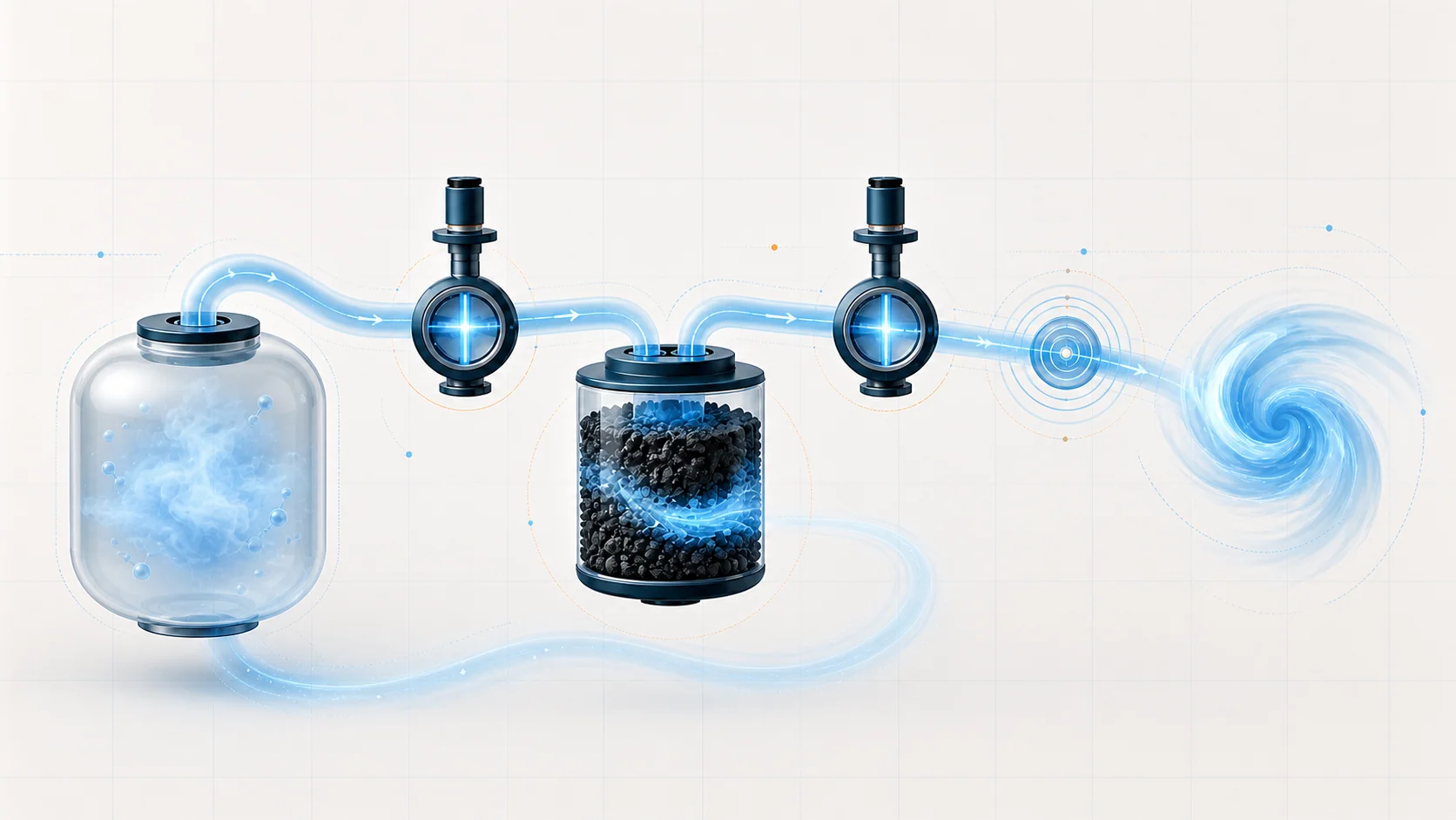
At a general gasoline-vehicle level, the evaporative emission control system, usually called EVAP, keeps fuel vapor from escaping directly into the atmosphere. Fuel in the tank produces vapor as conditions change. Instead of releasing that vapor outside, an EVAP system stores it in a charcoal canister and later routes it into the engine to be burned. Honda's exact control strategy, component design, and monitor-enabling conditions can vary by model year and configuration.
This system has two jobs that must work together:
- It must contain fuel vapor when the vehicle is parked or when the engine cannot use it.
- It must move the stored vapor into the engine at a controlled rate when operating conditions allow.
The ECM/PCM also checks whether the system can seal, purge, and vent as expected. An EVAP DTC therefore does not automatically identify a failed part. It identifies the type of system behavior that failed a monitor.
The main components on this Civic
The exact layout should always be confirmed in service information for the vehicle being repaired, but the diagnostic sources for this Civic revolve around the following components:
- Fuel tank and filler assembly: The tank, fuel fill pipe, fuel cap, vapor return path, tank-unit gasket, and related seals form part of the vapor boundary.
- EVAP canister: Charcoal inside the canister stores fuel vapor until the engine can purge it.
- EVAP canister purge valve: This valve controls the path between the canister and the engine intake. When commanded, intake vacuum draws stored vapor toward the engine.
- EVAP canister vent shut valve: The vent valve manages the fresh-air side of the system. It allows airflow during normal purge operation and can close the vent path when the ECM/PCM needs to test system sealing.
- Fuel tank pressure (FTP) sensor: The FTP sensor reports pressure and vacuum changes in the EVAP system. The ECM/PCM uses that feedback to decide whether commanded purge and vent actions produced the expected result.
- Hoses, tubes, ports, O-rings, and electrical circuits: The system depends on both an intact vapor path and correctly operating electrical controls. A disconnected line can create a leak code, while a damaged power or control circuit can prevent a valve from moving.
How purge, venting, and leak detection work together
In general EVAP operation, the ECM/PCM commands the purge valve to meter vapor toward the intake. The vent side provides a controlled source of fresh air through the canister so vapor can move without placing unintended pressure or vacuum on the tank.
During onboard monitoring, the ECM/PCM can change purge and vent commands and evaluate FTP sensor response under defined enabling conditions. Honda service procedures may separately use HDS bidirectional commands to isolate the system. Those technician-commanded tests support diagnosis, but they should not be assumed to reproduce the onboard monitor sequence exactly.
The important diagnostic question is not simply whether a valve clicks. It is whether the complete system responds correctly:
- Can the vapor system seal when commanded?
- Does pressure or vacuum change when purge flow is requested?
- Can the system return toward atmospheric pressure when it should vent?
- Do the valve circuits carry the expected power and control signals?
The monitor only runs under defined operating conditions. Fuel level, temperature, engine operation, and captured freeze-frame conditions can all matter. This is why clearing a code and immediately seeing no fault is not proof of a repair. The monitor may not have run yet.
What the related DTCs are telling you
These codes cover several EVAP failure categories plus one routing/referral DTC:
| DTC | Diagnostic category | What it directs you to prove |
|---|---|---|
| P0455 | Large leak or inability to seal | Whether the cap, filler area, vapor lines, valves, canister, tank seals, and related joints can hold the commanded condition |
| P0456 | Very small leak | The same general sealing path as P0455, but with extra attention to small or intermittent sealing losses |
| P0497 | Low purge flow | Whether the purge valve, purge line, canister port, vent path, and FTP feedback allow the expected flow response |
| P0498 | Vent shut valve circuit low voltage | Whether the valve has power, the valve winding is electrically sound, and the control circuit is not open or shorted |
| P2422 | Vent path appears stuck closed or restricted | Whether the physical vent path can return the system toward atmospheric pressure and whether the FTP sensor reports that change accurately |
| P145C | Purge-flow routing/referral DTC | If P145C is stored alone, the 2015 source routes diagnosis to both P0496 and P0497 procedures using P145C freeze data. If P0496 or P0497 is stored with it, diagnose the companion code first. P0496 requires its applicable service procedure and is outside this overview's diagnostic scope. |
The categories matter. A leak code, a flow code, a restriction code, and an electrical circuit code should not begin with the same parts-replacement decision.
What the driver may notice
Many EVAP faults do not create an obvious drivability complaint. The vehicle may run normally while the malfunction indicator lamp is on. Depending on the failure, the driver or technician may also encounter:
- an EVAP or emissions readiness monitor that will not complete;
- a failed emissions inspection because a DTC is stored or readiness is incomplete;
- a fuel-vapor odor when the system has an external leak;
- a fault that appears only under certain fuel-level, temperature, or driving conditions.
A lack of drivability symptoms does not make the code unimportant and does not narrow the failed section. A leak, valve, circuit, sensor, or intermittent connection can exist while the engine appears to run normally. Use the stored DTC and the applicable tests to classify the fault.
Safety before testing
Fuel vapor is flammable. Work in a properly ventilated area, eliminate ignition sources, and follow the applicable Honda service precautions. Use equipment approved for EVAP testing, and never use unregulated shop air to pressurize the system. Stop testing if liquid fuel leakage is present and correct that hazard before continuing. Apply only the pressure or vacuum specified by the exact service procedure.
Failure categories represented by these DTCs
1. The system cannot seal
A loose, incorrect, or damaged fuel cap is only one possibility. The filler-neck sealing surface, cap tether position, vapor recirculation tube, purge line, canister connections, valve seals, FTP sensor seal, tank-unit gasket, or tank can also allow a leak.
Large and very small leak codes both require evidence-based leak isolation. The difference in code description does not identify which component is leaking and does not justify guessing at a part.
2. Purge flow is restricted or does not occur
Low purge flow can result from a restricted or damaged purge line, a purge valve that does not provide the expected path, a blocked canister port, a vent-side problem that prevents airflow, or FTP feedback that does not respond correctly.
The useful question is: when purge is commanded and the rest of the system is placed in the required state, where does the expected vacuum response stop?
3. The system cannot vent
A restricted vent hose or drain joint, corrosion at the vent shut valve, a valve that does not move, a restricted FTP vent hose or port, or an internally restricted canister can make tank pressure remain abnormal when the system should be open to atmosphere.
P2422 does not identify a guaranteed failed vent valve. Diagnosis must evaluate both physical venting and the accuracy of FTP reporting according to the applicable service procedure.
4. A valve has an electrical fault
P0498 is different from a mechanical venting code. Its diagnostic path checks the valve power feed, the valve winding, and the control wire between the valve and the PCM. Connector damage, loose terminals, an open circuit, or a short to ground can all prevent proper operation.
Consider PCM software or PCM replacement only when the applicable service procedure reaches that decision after its required valve and circuit checks.
5. Sensor feedback is misleading
The ECM/PCM cannot evaluate purge, sealing, or venting correctly without believable FTP sensor feedback. A sensor that does not respond, a restricted sensor vent hose or port, a sealing problem around the sensor, or an internal canister restriction can all change what the scan tool shows.
Do not condemn the FTP sensor only because its reading is unexpected. First determine whether the sensor is being exposed to the pressure condition you think it is.
A practical diagnostic strategy
Step 1: Confirm the exact vehicle and collect the evidence
Verify the year, engine, body configuration, and applicable service information. Record all pending and confirmed DTCs, freeze-frame data, and any on-board snapshot before clearing anything. Code combinations are especially important for P145C because they determine which purge-flow path should be followed.
Step 2: Classify the fault before testing parts
Place the fault into one of five working categories:
- sealing or leak detection;
- purge-flow performance;
- vent restriction or mechanical valve operation;
- electrical circuit control;
- FTP sensor feedback or plausibility.
FTP validation is also a cross-cutting requirement: sealing, purge, and vent conclusions are only useful when the displayed pressure response is believable. This classification determines whether the next useful tool is visual inspection, controlled vacuum testing, scan-tool actuation with FTP observation, sensor validation, or electrical measurement.
Step 3: Perform the applicable basic visual checks
Follow the applicable procedure's basic inspection order. For leak faults, this may begin at the cap, filler sealing surface, accessible hoses, tube connections, and recently disturbed components. For flow or vent faults, inspect the relevant line for poor connection, damage, pinching, or blockage. For circuit faults, inspect the valve connector, terminals, and harness routing before replacing the valve. This is a test-order recommendation, not a claim that one area fails more often than another.
Step 4: Reproduce the fault with the correct scan-tool function
Use Honda HDS, or a bidirectional scan tool verified to support the required Honda EVAP functions for the exact vehicle. A generic scanner may read DTCs or FTP data without supporting the required bidirectional valve commands, EVAP function tests, or monitor-status functions. Use the exact Honda procedure for the vehicle and DTC to decide which tool functions, valve states, engine conditions, and sensor responses are required.
An intermittent result should send you back to captured operating conditions and connector checks. It should not automatically be treated as a passed repair.
Step 5: Divide the system into smaller sections
Isolation is more reliable than testing the whole EVAP system as one volume. Depending on the code, the service path separates the purge valve, purge line, canister side, vent line, filler side, FTP sensor vent path, and tank sealing area. Each result should eliminate one section or direct the next test.
Use only the pressure or vacuum specified by the applicable service procedure. Excessive pressure or vacuum can damage EVAP components or the fuel tank.
Step 6: Test electrical faults as circuits
When the code identifies a low-voltage circuit, use the exact service-information sequence to test the applicable power feed, valve winding, control wiring, and terminal condition. A valve that is mechanically capable of moving can still fail electrically, and a good valve cannot operate through an open power feed or damaged control wire.
Step 7: Verify the repair under the same logic that detected the fault
Reassemble the system completely, perform any specified ECM/PCM reset or idle-learn steps, and run the applicable EVAP function test or OBD monitor verification. Confirm that the relevant result passes and that no related pending code returns.
Readiness matters. A cleared code with an incomplete monitor is not the same as a verified repair.
Avoid the EVAP parts cannon
The same component names appear in several EVAP code paths, but they do not fail in the same way. A vent valve can leak, stick, become restricted, lose power, have a damaged control wire, or operate correctly while another part creates misleading FTP behavior.
The efficient approach is to make each test answer one question:
- Is the fault present now?
- Is the vapor path sealed?
- Does the purge path flow?
- Can the vent path open and close?
- Does the FTP sensor respond to a known change?
- Does the electrical circuit support the commanded valve state?
Once the failed section is proven, the linked STEP DTC guide provides educational model-specific context. Verify the exact test sequence, specifications, connector information, and repair-verification steps in service information for the vehicle's year and configuration.
Final takeaway
On the 2010-2015 Honda Civic 1.8 Gas, the EVAP system is a controlled vapor-storage, purge, vent, and self-test system. The ECM/PCM commands valves and evaluates FTP sensor response, but a DTC reports failed behavior rather than naming a guaranteed bad part.
Begin with vehicle applicability and stored evidence, classify the code, inspect the relevant path, command the system, observe FTP response, and isolate the failure before replacing anything. That method turns a broad EVAP complaint into a small, testable section of the system.