What this code means
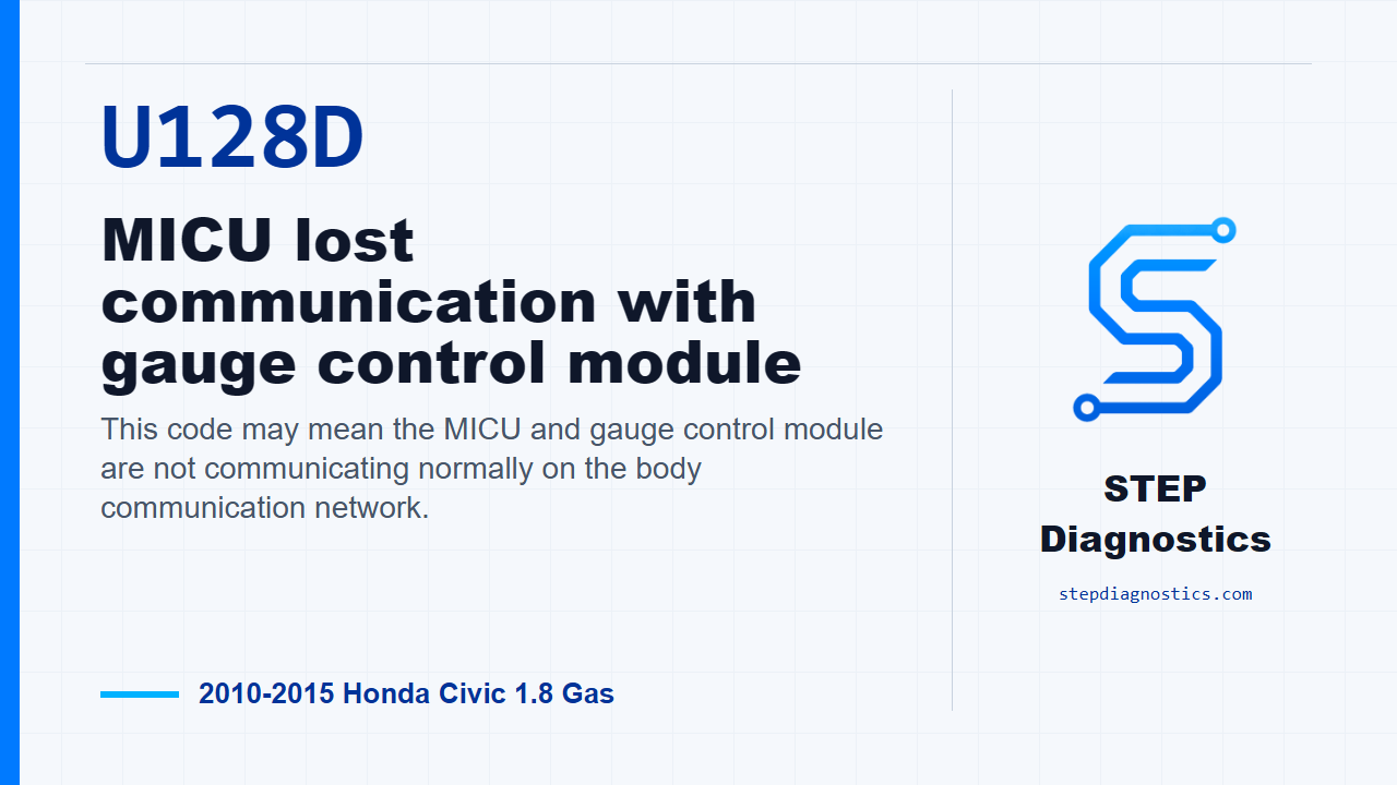
This code may mean the MICU and gauge control module are not communicating normally on the body communication network.
What the vehicle may do
- The vehicle may store a communication-related code with few obvious symptoms.
- Gauge or cluster operation may be affected during the fault.
- The concern can be intermittent if a connection opens only under certain conditions.
Possible fault areas
- Possible backup power feed problem
- Possible fuse or short-to-ground issue
- Possible gauge control module ground problem
- Possible loose or poor connector contact
- Possible open or poor connection in the B-CAN wiring between the MICU and gauge control module
Diagnostic path
Opening context
On this Civic, U128D means the MICU has lost communication with the gauge control module. In plain terms, the body control side and the gauge side may not be talking over the B-CAN circuit the way they should. The vehicle may show gauge or cluster-related symptoms, or it may simply store the code during a network fault. The broad fault areas are possible power feed issues, ground issues, connector problems, or an open or poor connection in the B-CAN wiring between the MICU and the gauge control module. If other codes are present, check what they mean first and use the correct B-CAN diagnostic path for multiple-code situations.
Verify the code first
Start by verifying the problem. Clear the codes with the HDS, turn the ignition switch to LOCK (0), then turn it back to ON (II). Wait for at least 6 seconds, then check for codes again. If U128D comes right back, continue with the circuit checks. If it does not return, treat it as an intermittent failure for now. The system is OK at this time, so concentrate on loose terminals, poor connections, and anything that could intermittently break communication.
Check the backup power fuse
Next, check fuse No. A29, the 10 A fuse in the under-hood fuse and relay box. If the fuse is good, move on to the gauge control module power feed check. If the fuse is open, replace the fuse. If it blows again, repair the short to ground in the No. A29 fuse circuit before going any farther.
Check the gauge control module backup power feed
Now check the +B_BACK_UP feed at the gauge control module. Turn the ignition switch to LOCK (0), disconnect the gauge control module, tach, 32P connector, and measure voltage from connector No. 1, the WHT wire, to body ground. With the connector disconnected and the ignition in LOCK (0), you are looking for battery voltage on that feed. If battery voltage is present, go to the ground checks. If battery voltage is not present, repair the open or high resistance in that wire.
Check the gauge control module grounds
With the ignition still in LOCK (0) and the gauge control module 32P connector still disconnected, check the ground circuits one at a time. Check continuity from connector No. 4, the BLK wire, to body ground. Then check continuity from connector No. 32, the BRN wire, to body ground. If both ground checks have continuity, continue to the B-CAN wiring check. If continuity is missing, repair the open or high resistance in the ground wire, or repair the poor ground at G502 or G503.
Check the B-CAN wiring between the modules
For the network wiring check, disconnect the under-dash fuse and relay box connector K, the 12P connector. With the ignition in LOCK (0), the gauge control module 32P connector disconnected, and connector K disconnected, check continuity on the B_CAN-H circuit. Check between under-dash fuse and relay box connector K No. 2, the PNK wire, and gauge control module connector No. 30, also the PNK wire. If there is continuity on that check, the remaining fault direction is an open or poor connection in the B_CAN-L wire between the MICU and the gauge control module. If there is no continuity, the fault direction is an open or poor connection in the B_CAN-H wire between the MICU and the gauge control module.
Verify the repair
After the wiring, fuse, power, ground, or connector issue is corrected, verify the repair separately from the circuit testing. Clear the code, cycle the ignition the same way, allow the module communication to run again, and confirm U128D stays gone. The takeaway is simple: prove the code is current, prove the gauge module has its power and grounds, then isolate whether the B-CAN fault is on the high side or the low side. For more diagnostic training, visit stepdiagnostics.com.
Final check
U128D is approached as a communication circuit fault: confirm it is current, then check fuse power, module power, grounds, and the B-CAN wiring path.
For more guided automotive diagnostics, visit STEP Diagnostics.