What this code means
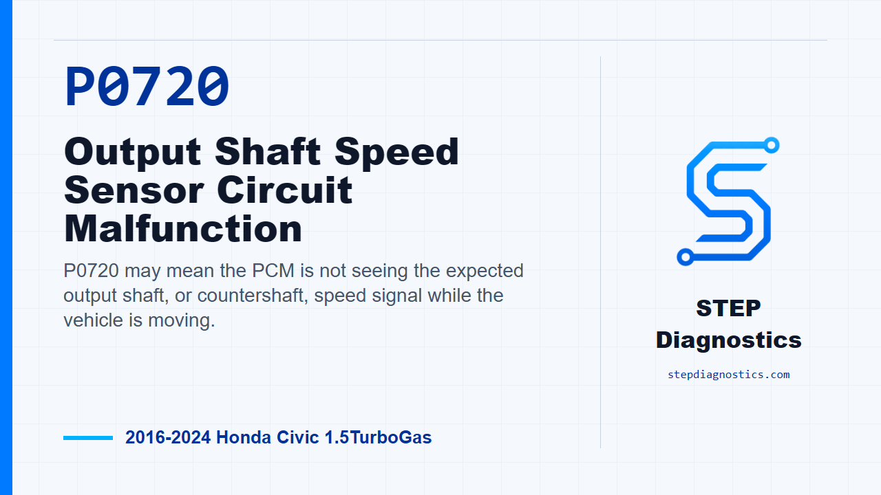
P0720 may mean the PCM is not seeing the expected output shaft, or countershaft, speed signal while the vehicle is moving.
What the vehicle may do
- The vehicle may have shift or drivability complaints.
- The speed signal data can appear missing or inconsistent during a road test.
- The code may set when the PCM sees vehicle movement from other speed inputs but not from the countershaft speed signal.
Possible fault areas
- A possible output shaft speed sensor signal issue.
- A possible wiring, connector, power, ground, or signal circuit issue.
- A possible related control module issue after other checks indicate normal conditions.
Diagnostic path
Open and frame the code
On this Civic, P0720 is an output shaft, or countershaft, speed sensor circuit fault. In plain language, the PCM may be seeing vehicle movement from the wheel speed side, but not seeing a matching countershaft speed signal. The driver may notice shift or drivability complaints, and the fault area can include the speed sensor circuit, the sensor side of the system, related wiring or connector issues, and, after the other checks pass, a possible PCM problem. Before going after the code, start with the basic system checks and make sure any broader vehicle issues are not steering the diagnosis off course.
How the PCM decides P0720 is present
The logic for this code is straightforward. If the output shaft, or countershaft, speed signal stays at 0 mph, or 0 km/h, while the wheel speed sensors show the vehicle is moving for the required amount of time, the PCM treats that as an abnormal signal and stores P0720. So the first job is not to guess at a part. The first job is to reproduce the failure and see whether the countershaft speed data actually drops out while the vehicle is being driven.
Reproduce the operating conditions
Start the engine. Hold the engine speed at 3,000 rpm with no load, in neutral, until the radiator fan comes on, then let the engine idle. After that, test-drive the vehicle for several minutes while watching the HDS countershaft speed data. If the HDS C Shaft Spd value does not show any vehicle speed while driving, the failure has been duplicated.
Inspect the output shaft speed sensor side
Once the failure is duplicated, move into the output shaft, or countershaft, speed sensor inspection. Disconnect the output shaft speed sensor 3P connector and perform the inspection table checks. The normal unit output voltage condition with IG Mode ON is about 5.0 V for each listed measurement. There is no direct method here to test the component by itself, so the diagnosis is made by checking the related parts of the circuit. If this inspection is normal, the diagnostic result points to a problem with the output shaft speed sensor. If it is abnormal, continue into the related circuit checks instead of jumping straight to a sensor call.
Check the VCC1, NC, and SG1 circuits
Next, prepare for the VCC1, NC, and SG1 circuit inspection. Disconnect the output shaft speed sensor 3P connector and PCM connector E, the 80P connector. Before disconnecting the PCM connector, jump the SCS line with the HDS and wait more than 1 minute. Then perform the circuit inspection table checks. With IG Mode OFF, the normal condition for the VCC1 open-wire check is less than 1 Ω. The SG1 open-wire check is also less than 1 Ω, and the NC open-wire check is less than 1 Ω. The NC short-to-ground check should show that the circuit is not shorted. If these checks are abnormal, the problem is in the circuit. Do not guess at terminal positions; make sure the connector and terminal identification is correct before measuring.
PCM conclusion after the other checks pass
If the other inspection items indicate normal conditions, then the remaining conclusion is a PCM problem. That does not mean skipping the earlier checks. The PCM conclusion only comes after the sensor-side inspection and the VCC1, NC, and SG1 circuit checks have been worked in order. If something in the earlier path does not line up, pause, recheck that part of the diagnostic path, and avoid guessing.
Verify the repair
After the fault area has been corrected, keep verification separate from testing. Run the vehicle again under the same warm-up and road-test approach used to duplicate the fault, watch the countershaft speed data, and confirm the code stays gone. The takeaway is simple: for P0720, prove the missing countershaft speed signal first, then separate sensor-side results from circuit results before calling the PCM. For more diagnostic training, visit stepdiagnostics.com.
Final check
Prove the missing countershaft speed signal, then work through the sensor-side and circuit checks in order before drawing a PCM conclusion.
For more guided automotive diagnostics, visit STEP Diagnostics.