What this code means
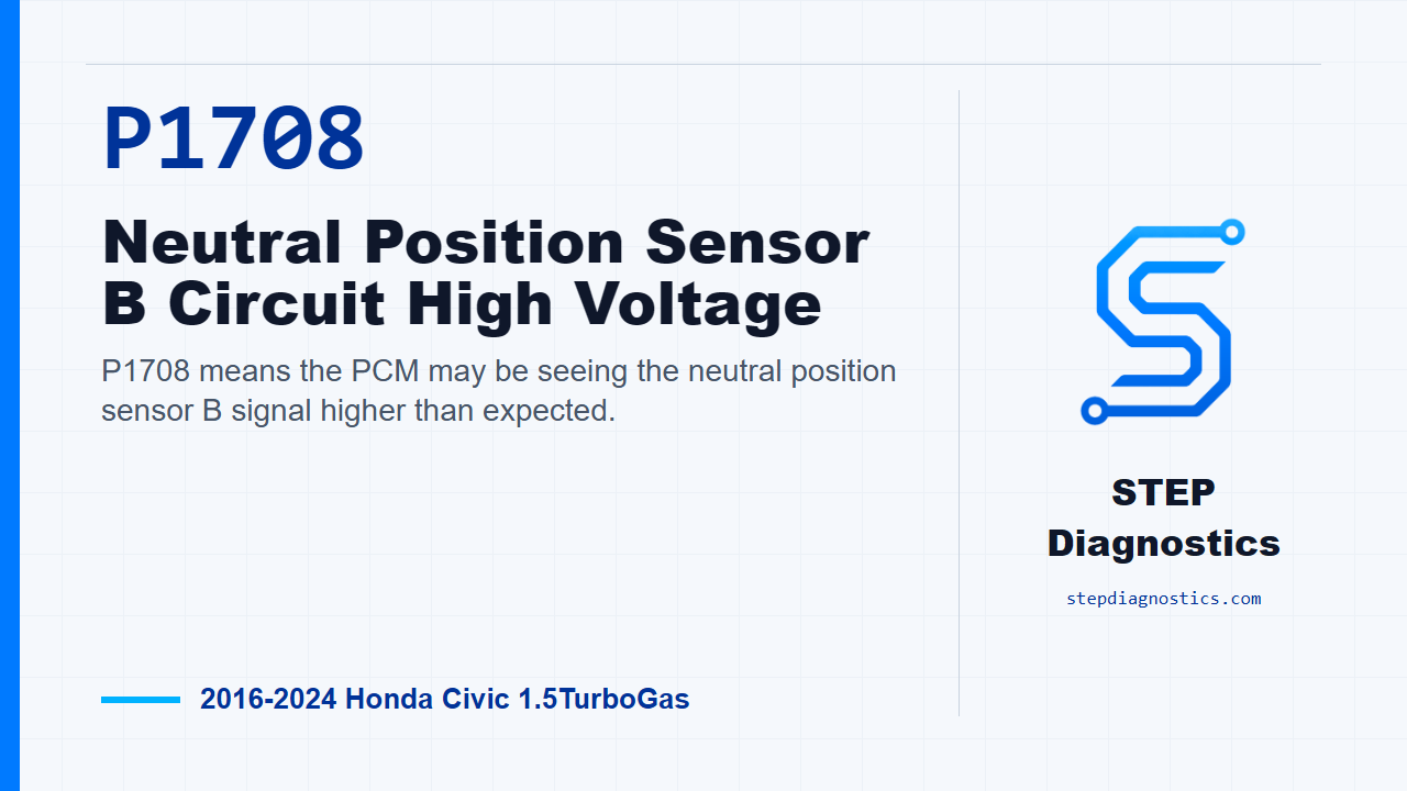
P1708 means the PCM may be seeing the neutral position sensor B signal higher than expected.
What the vehicle may do
- The vehicle may turn on a warning light.
- The PCM may not interpret the neutral position input correctly.
- Shift, start, or neutral-related behavior can be affected depending on the failure.
Possible fault areas
- Possible neutral position sensor signal issue.
- Possible wiring, connector, open, or short-to-power issue in the related circuit.
- Possible PCM input issue after other checks pass.
Diagnostic path
Open and code context
Today we’re working through P1708 on a 2016 to 2024 Honda Civic with the 1.5 turbo engine. In plain terms, the PCM is seeing the neutral position sensor B signal higher than it expects. Depending on the vehicle and the failure, this may show up as a warning light, an incorrect neutral input, or other shift or start-related behavior. The broad areas to keep in mind are the neutral position sensor signal, the sensor circuit and connectors, and the PCM input. If another related neutral-position code is present at the same time, use that as context to decide which shared part of the circuit to focus on first, but keep this diagnosis centered on P1708.
Start with the basic checks and confirm the fault
Before getting into pin tests, start with the basic system checks. Make sure the complaint and code information make sense, and don’t skip over obvious connector or harness issues. For confirmation, turn the vehicle to the ON mode. This code sets when the neutral position sensor B output voltage is higher than the specified value, so the first goal is to see whether the scan data and circuit checks point toward the sensor side, the wiring side, or the PCM side.
Check the neutral position sensor signal path first
The component itself does not have a direct standalone test in this path, so the diagnosis is done by checking the related parts of the circuit. Begin the neutral position sensor inspection with the neutral position sensor 4P connector disconnected. Turn the vehicle to the ON mode, then look at the HDS Neutral Position Sensor 2 value. The normal value at this point is 0 V. Next, with that same 4P connector disconnected, continue the unit output voltage inspection. With the circuit ON, the normal output is About 5.0 V. If this neutral position sensor inspection checks normal, the path points to a problem with the neutral position sensor. If it does not check normal, continue looking at the related circuit components instead of guessing at the sensor.
Move into the NSS2 and SG1 circuit checks
Before disconnecting the PCM connector, jump the SCS line with the HDS and wait more than 1 minute. Then set up the circuit inspection with the neutral position sensor 4P connector disconnected and PCM connector E, the 80P connector, disconnected. The circuit checks are split between the SG1 open-wire check and the NSS2 short-to-power check. For the SG1 open-wire inspection with the circuit OFF, normal is less than 1 Ω. For the NSS2 shorted-to-power inspection with the circuit ON, normal is not shorted. If either of those checks is abnormal, the problem is in the circuit.
PCM decision point
If the neutral position sensor inspection and the NSS2 and SG1 circuit inspection all indicate normal conditions, the remaining fault area in this diagnostic path is the PCM. That does not mean skipping the earlier tests. It means the PCM only becomes the conclusion after the sensor-related checks and circuit checks have already passed.
Verify and close
After correcting the fault that the testing proves, verify the repair separately from the testing process. Confirm the code stays gone and the neutral position input behaves normally. The key takeaway is to let the sensor signal check, the circuit checks, and then the PCM decision point lead the diagnosis in order. For more diagnostic training, visit stepdiagnostics.com.
Final check
P1708 is often best diagnosed by checking the sensor signal path first, then the related circuit, and only then considering the PCM if the earlier checks are normal.
For more guided automotive diagnostics, visit STEP Diagnostics.