What this code means
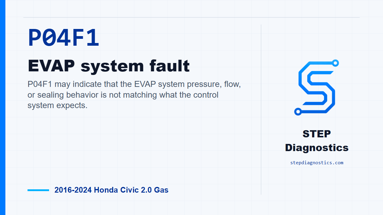
P04F1 may indicate that the EVAP system pressure, flow, or sealing behavior is not matching what the control system expects.
What the vehicle may do
- The vehicle may turn on a warning light.
- The driver may not notice a major drivability change.
- The fault can sometimes be associated with EVAP self-test behavior or refueling-related complaints.
Possible fault areas
- Possible purge line connection, blockage, damage, or restriction concerns.
- Possible purge valve or purge tube concern.
- Possible FTP sensor response concern.
- Possible EVAP canister or vent shut valve concern.
Diagnostic path
Opening context
On this 2016 to 2024 Honda Civic with the 2.0 gas engine, P04F1 is an EVAP system fault. In plain terms, the vehicle may be seeing an EVAP flow, pressure, or sealing behavior that does not match what the control system expects. The driver may not notice much beyond a warning light, but EVAP-related faults can sometimes show up after refueling or during self-tests. The broad areas to keep in mind are possible restrictions or damage in the purge plumbing, a purge valve issue, FTP sensor response, the EVAP canister, or the vent shut valve. Start with the basic system checks, then follow a structured diagnostic approach instead of guessing at parts.
Duplicate the fault first
Begin by turning the vehicle to the ON mode. Then run the HDS function test for this fault. If the function test result is not OK, the failure has been duplicated, and you can move into the EVAP inspections with confidence that the condition is active enough to test.
Check the purge line visually
Next, inspect the EVAP canister purge line between the intake manifold and the EVAP canister. Look for poor connections, blockage, or damage. The expected condition is that the connections are OK, with no blockage or damage. If that visual check is abnormal, the fault is in the parts along that purge line between the intake manifold and the canister.
Vacuum-check the purge line
Now isolate the purge line. Disconnect the vacuum hose, or purge line, from the EVAP canister purge valve. Then disconnect the EVAP canister purge line from the EVAP canister. Set up the T-fitting with the vacuum/pressure gauge, 0-4 inHg, and the vacuum pump/gauge, 0-30 inHg, on the EVAP canister purge line. Slowly apply about 2 kPa (0.6 inHg, 15 mmHg) of vacuum to the hose. For this check, the EVAP canister purge line should not hold vacuum. If the result is abnormal, the problem is in the purge line parts between the EVAP canister purge valve and the EVAP canister.
Inspect the purge tube
After that, check the purge tube between the intake manifold and the EVAP canister purge valve. You are looking for an excessive bend, foreign object clogging, or any restriction. The expected condition is no excessive bend, no foreign object clog, and no restriction. If this inspection is abnormal, the purge tube is the fault area.
Check FTP sensor response
Next is the FTP sensor functional check. Remove the FTP sensor while keeping its connector connected. Connect the T-fitting to the vacuum pump/gauge, 0-30 inHg, and the vacuum/pressure gauge, 0-4 inHg, to the FTP sensor. Turn the vehicle to the ON mode and watch the HDS FTP Sensor value. Slowly apply about 1.3 kPa (0.4 inHg, 10 mmHg) of vacuum to the hose. Be careful not to exceed that vacuum, because the FTP sensor can be damaged. Then confirm the FTP Sensor value again. The expected result is that the current value and the recorded value on the HDS FTP Sensor are different. If that check is abnormal, the problem is with the FTP sensor.
Check the purge valve
The purge valve test comes next, with the purge tube already confirmed normal. There is one important point here: this test can be done before the other individual inspections because it includes the following inspection items, but if it fails, you still need to continue through the individual checks to find which item actually failed. For the purge valve inspection, disconnect the vacuum hose from the EVAP canister purge valve. Connect the T-fitting, the vacuum/pressure gauge, 0-4 inHg, and the vacuum pump/gauge, 0-30 inHg, to the EVAP canister purge valve. Turn the vehicle to the ON mode, command HDS PCS(CPV) ON, and slowly apply about 2 kPa (0.6 inHg, 15 mmHg) of vacuum to the hose. The expected result is that vacuum is not held. If that result is abnormal, the EVAP canister purge valve is the fault area.
Check the EVAP canister
Then move to the EVAP canister inspection, with the EVAP canister purge line already confirmed normal. The EVAP canister vent shut valve is removed for this check. In the engine compartment, disconnect the vacuum hose, or purge line, from the EVAP canister purge valve. Connect the T-fitting, vacuum/pressure gauge, 0-4 inHg, and vacuum pump/gauge, 0-30 inHg, to the vacuum hose. Slowly apply about 2 kPa (0.6 inHg, 15 mmHg) of vacuum to the hose. The expected result is that the vacuum is not held. If that check is abnormal, the EVAP canister is the fault area.
Final fault isolation
If the other inspection items all indicate a normal condition, then the remaining fault area is the EVAP canister vent shut valve. At that point, do not circle back and guess at parts that have already passed. Pause, recheck the earlier diagnostic path if anything does not line up, and keep the decision tied to the actual failed inspection.
Takeaway and CTA
The key with P04F1 is to prove the EVAP path one section at a time: duplicate the fault, inspect the purge plumbing, check sensor response, then separate the purge valve, canister, and vent shut valve decisions. For more diagnostic training, visit stepdiagnostics.com.
Final check
P04F1 is best approached by isolating each EVAP section and letting the failed test identify the fault area.
For more guided automotive diagnostics, visit STEP Diagnostics.