What this code means
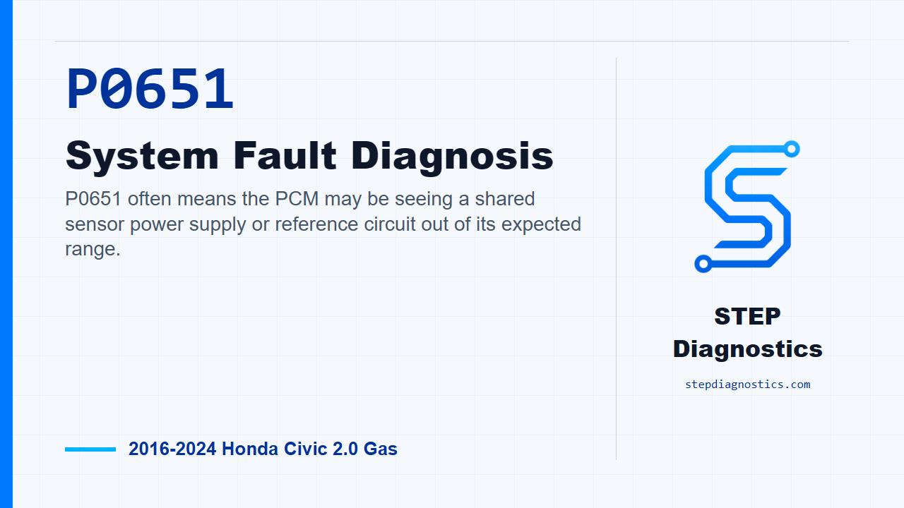
P0651 often means the PCM may be seeing a shared sensor power supply or reference circuit out of its expected range.
What the vehicle may do
- The vehicle may turn on a warning light.
- The engine may have drivability symptoms depending on which sensor supply path is affected.
- Some sensor readings may look unreasonable if the shared supply is pulled down or pulled high.
Possible fault areas
- Possible VCC2, VCC5, or VCC6 circuit fault.
- Possible wiring or connector issue on a shared sensor supply path.
- Possible sensor connected to the shared supply circuit affecting the circuit.
- Possible PCM-side concern after the external circuit checks normal.
Diagnostic path
Open on what P0651 is pointing at
On this 2016 through 2024 Honda Civic with the 2.0 liter non-turbo engine, P0651 means the PCM is seeing a problem with a shared sensor power supply circuit. In plain terms, the computer expects that sensor feed to stay in range, and when it does not, it can set this code. The vehicle may have drivability complaints, warning lights, or limited response depending on which part of the circuit is affected. The broad possible fault areas are the VCC2, VCC5, and VCC6 supply circuits, the sensors connected to those circuits, their connectors and wiring, or, after the outside circuit checks good, the PCM side of the circuit.
Start with the basic system checks
Before jumping straight into the circuit tests, start with the basic system checks and follow a structured diagnostic approach. If other codes are present, understand what they mean first, because a shared sensor supply fault can make more than one input look wrong. For P0651 itself, the confirmation step is simple: turn the vehicle to ON mode and see whether the fault is present under that condition.
Prepare for the VCC circuit inspection
For the VCC2, VCC5, and VCC6 circuit inspection, protect the PCM before disconnecting it. Jump the SCS line with the HDS, then wait more than 1 minute before disconnecting the PCM connector. Once that is done, disconnect PCM connector A, PCM connector E, and the sensors tied into these supply circuits. That group includes the camshaft position sensors, MAP sensor, engine oil pressure sensor, accelerator pedal position sensor, A/C pressure sensor, and the model-dependent fuel tank pressure and brake booster pressure sensors where equipped.
Check for shorts on VCC2, VCC5, and VCC6
Now inspect the VCC2, VCC5, and VCC6 circuits in order. The goal here is not to condemn a sensor yet. First, prove the external wiring is not shorted. With the PCM connectors disconnected, check VCC2 shorted to ground with IG Mode OFF. The normal result is not shorted. Then do the same ground-short check on VCC5, and then on VCC6, again with IG Mode OFF, and each one should be not shorted. After that, switch to the short-to-power checks with IG Mode ON. Check VCC2, then VCC5, then VCC6. Each normal result is not shorted. If any of these checks is abnormal, stay with the circuit problem before moving on. Also, do not assume the diagrammed area is the whole inspection area; make sure the connector and terminal identification is positive before probing. If you cannot confirm the test points, pause, recheck the earlier diagnostic path, and avoid guessing.
Only after the external circuit checks normal, check the PCM path
Once the external circuit has been confirmed normal, move to the PCM inspection. Disconnect the same group of sensors from the VCC2, VCC5, and VCC6 circuits, then perform the confirmation procedure again. The normal result is that P0651 is not indicated. If the result is abnormal at this point, the diagnostic path points to a problem with the PCM. There is an important workflow note here: this PCM check can be run early because it covers several inspection items at once, but if it fails, you still have to continue with the individual checks to identify which item failed. Do not skip that isolation work.
Reconnect the connected components one at a time
If the external circuit is normal and the PCM is normal, isolate the component side. Start with the affected sensors disconnected, then use the HDS to watch for pending or confirmed P0651 while reconnecting the components one at a time. Work through the camshaft position sensors, MAP sensor, engine oil pressure sensor, accelerator pedal position sensor, A/C pressure sensor, and the model-dependent fuel tank pressure and brake booster pressure sensors where equipped. The normal result is that P0651 is not indicated. If the code appears when one component is reconnected, the problem is with the component that caused the DTC when it was reconnected, or its immediate connection to that shared supply path. This grouped test can be useful early, but if it fails, break the circuit back down and isolate the exact item instead of guessing.
Close and takeaway
The key with P0651 is to keep the order clean: confirm the code, protect the PCM before disconnecting, prove VCC2, VCC5, and VCC6 are not shorted, check the PCM path only after the outside circuit is normal, then reconnect the shared-supply components one at a time to see what brings the code back. Take your time and let the test result point to the fault. For more diagnostic training, visit stepdiagnostics.com.
Final check
P0651 is best handled by isolating the shared supply circuit first, then separating PCM-side and connected-component causes without guessing.
For more guided automotive diagnostics, visit STEP Diagnostics.