What this system does
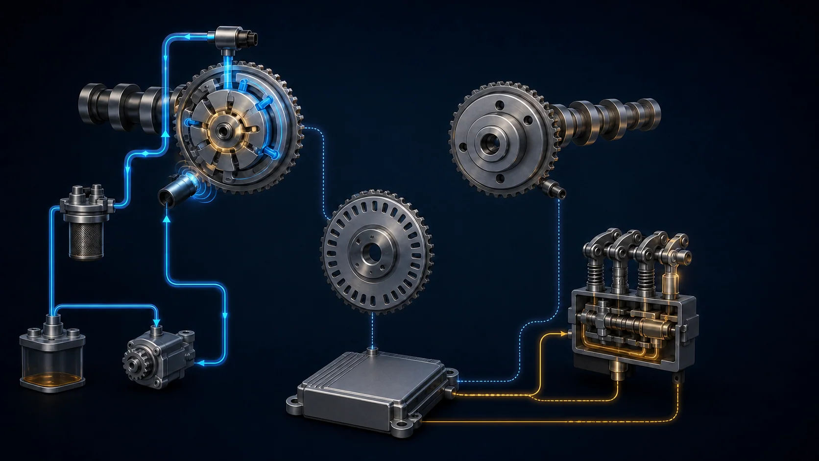
This engine depends on several related systems that must agree with one another. The timing chain establishes the base relationship between the crankshaft and camshafts. The crankshaft position (CKP) and camshaft position (CMP) sensors report rotational position to the powertrain control module (PCM). Variable Timing Control (VTC) uses engine oil pressure to move the intake camshaft relative to base timing. The VTEC rocker-arm system uses oil pressure to change intake-valve lift when operating conditions call for it.
The PCM therefore evaluates more than one kind of evidence:
- CKP pulses provide the main crankshaft-speed and position reference.
- CMP sensor A reports intake-camshaft position, while CMP sensor B reports exhaust-camshaft position.
- The PCM compares crank and cam signals to judge phase and synchronization.
- A PCM-controlled VTC oil control solenoid routes oil to the intake-cam actuator.
- The PCM uses CMP sensor A feedback to judge whether actual intake-cam movement follows the request.
- A separate rocker-arm oil control solenoid and pressure switch control and monitor the VTEC hydraulic state.
These functions share the PCM, engine oil, wiring, connectors, and mechanical timing hardware, but their DTCs do not prove the same failure. A pulse-interruption code, a phase code, a VTC performance code, a pressure-switch code, and a solenoid-circuit code require different proof.
Applicability note: Vehicle records support 2.4-liter CR-V applications at the 2010 and 2016 endpoints used for this overview. The detailed system descriptions and diagnostic procedures reviewed here are from the 2016 K24W9 application. Use the article as system-level orientation; current service information for the exact CR-V controls component arrangement, scan data, commands, thresholds, wiring, and repair procedures.
The main functional sections
- Base mechanical timing: The chain, sprockets, tensioning components, crankshaft, camshafts, and indexed timing references establish the physical crank-to-cam relationship.
- CKP and CMP signal channels: Each channel includes the sensor, connector, harness, electrical paths, rotating pulse plate or target, and PCM input. A usable signal must retain its expected pulse pattern during cranking and running.
- Intake VTC actuator: A vane-type actuator at the intake camshaft advances or retards intake-cam timing. A lock mechanism holds the actuator in its base retarded position when the engine is stopped.
- VTC oil control: The PCM commands a solenoid valve that meters pressurized oil to the advance or retard side of the actuator. CMP sensor A closes the feedback loop.
- VTEC rocker-arm control: A rocker-arm oil control valve routes pressure to switching pistons in the intake rocker arms. The pressure switch reports the hydraulic state to the PCM.
- PCM command and monitoring: The PCM uses position signals and other operating inputs to command VTC and VTEC, monitor response, detect signal interruptions, and determine whether the mechanical relationship remains plausible.
Normal operation in four layers
1. Base timing provides the reference
The timing chain must keep the crankshaft and both camshafts in their intended base relationship. VTC can move the intake camshaft through a controlled range, but it cannot correct a chain installed on the wrong marks, a damaged target, a shifted mechanical relationship, or an actuator assembled outside its proper reference position.
Base timing matters even when the engine starts and runs. A small phase error may appear first as a correlation or VTC performance problem rather than an immediate no-start.
2. CKP and CMP signals establish engine position
The CKP signal provides the detailed rotational reference. CMP sensor A identifies intake-cam phase; CMP sensor B identifies exhaust-cam phase. The PCM uses the relationship among these signals to identify engine position and evaluate timing.
A signal can fail without disappearing permanently. Heat, vibration, harness movement, poor terminal contact, sensor damage, or a pulse-plate concern can create missing or irregular pulses. That is why intermittent CKP or CMP DTCs should be treated first as signal-quality problems, not automatic proof of a slipped chain.
3. VTC changes intake-cam phase with oil pressure
When operating conditions call for a timing change, the PCM commands the VTC oil control solenoid. The valve directs oil to the advance or retard chamber in the intake-cam actuator, and the actuator changes intake-cam angle. CMP sensor A reports the resulting angle so the PCM can adjust the command.
This is a command-versus-response system. A correct electrical command cannot move the actuator if oil pressure is inadequate, an oil passage is restricted, the valve sticks, or the actuator cannot move smoothly. Conversely, acceptable base oil pressure does not prove the solenoid, actuator, feedback signal, or mechanical timing is correct.
4. VTEC changes intake-valve lift
The rocker-arm oil control solenoid switches the intake-side VTEC hydraulic circuit. When commanded, oil pressure moves switching pistons so the applicable rocker arms follow the intended cam-lobe profile. The rocker-arm oil pressure switch lets the PCM monitor whether the hydraulic state agrees with the command.
The solenoid circuit and the pressure-switch circuit answer different questions. P2649 directs testing of the solenoid and its control path. In the exact 2016 P2647 path, the technician checks oil level, then the pressure switch, its wiring and ground path, and finally PCM software or PCM evaluation. P2647 does not by itself authorize a control-valve, passage, or mechanical-pressure diagnosis; follow current service information if other evidence directs those tests.
What the related DTCs are telling you
| DTC | Diagnostic category | What it directs you to prove |
|---|---|---|
| P0339 | CKP signal intermittent interruption | Whether connector fit, wiring, the sensor, its target relationship, or the PCM input explains missing or irregular crank pulses |
| P0341 | CMP sensor A and CKP phase disagreement | Whether direct signal faults, VTC oil control, actuator response, or base cam timing explains the incorrect relationship |
| P0344 | Intake CMP signal intermittent interruption | Whether the intake CMP circuit, connector, sensor, pulse plate, or PCM input explains abnormal or missing pulses |
| P0369 | Exhaust CMP signal intermittent interruption | Whether the exhaust CMP circuit, connector, sensor, pulse plate, or PCM input explains abnormal or missing pulses |
| P1009 | VTC advance performance | Whether the VTC solenoid, oil passages, actuator, base timing, or feedback explains an intake-cam response that does not agree with the command |
| P2647 | Rocker-arm oil-pressure-switch circuit high voltage | Whether oil level, the pressure switch, its connector/wiring/ground path, or PCM software/control explains the high-voltage result |
| P2649 | Rocker-arm oil-control-solenoid circuit high | Whether the solenoid winding, connector, harness, PCM control circuit, or driver explains the electrical result |
The code set determines the diagnostic order. A direct CKP or CMP pulse-interruption code can make a phase result secondary. A VTC response problem should be understood before P0341 is used to justify mechanical disassembly. P2647 and P2649 involve the same general VTEC control area, but one focuses on the pressure-switch circuit and the other on the electrical solenoid path. Follow the related-code priority in current service information; when the direct P2649 solenoid-circuit fault is present with P2647, prove that electrical path before using the pressure-switch result to judge the system.
What the driver or technician may notice
Possible observations include:
- a malfunction indicator lamp with little obvious drivability change;
- intermittent hard starting, extended cranking, stumble, or stall if a position signal drops out;
- rough idle, hesitation, reduced power, or inconsistent response when cam timing or valve lift does not change as intended;
- an intermittent problem that appears with temperature, vibration, harness movement, or a particular engine speed and load;
- actual intake-cam response that is slow, stuck, unstable, or unable to return;
- an abnormal rattle or mechanical noise that requires base-engine and timing inspection;
- several position, VTC, VTEC, oil-pressure, or misfire-related codes that must be prioritized together.
None of these symptoms proves that a sensor, solenoid, actuator, timing chain, or PCM has failed. Starting, charging, ignition, fuel, airflow, lubrication, and other base-engine faults can create similar complaints.
Safety comes before timing diagnosis
Running signal and VTC tests can place the technician near belts, pulleys, a cooling fan, hot engine parts, and moving linkages. Secure clothing, test leads, and tools. Keep hands clear of rotating components, and remember that an electric fan can start unexpectedly.
Do not jumper, power, ground, or back-probe a CKP, CMP, VTC, or rocker-arm control circuit unless current service information identifies the correct terminals, fused test method, and vehicle state. A wrong connection can damage a sensor or PCM driver.
Oil-pressure testing opens a pressurized lubrication circuit and may require the engine to run. Use the specified adapter and gauge, confirm secure connections before starting, wear appropriate eye protection, and stop the engine immediately if pressure is absent.
Mechanical timing or actuator service requires controlled engine positioning, exact timing references, correct tools, fasteners, sealants, and post-repair checks. The exact Honda procedure for the vehicle controls those steps.
Common failure categories
Position-sensor signal or circuit fault
Poor terminal fit, corrosion, damaged wiring, heat, vibration, contamination, sensor failure, or a target concern can interrupt CKP or CMP pulses. A normal static voltage reading does not prove the pulse train remains usable while the engine is cranking, running, or moving through temperature and vibration changes.
VTC hydraulic or actuator fault
Incorrect oil level or condition, inadequate pressure, a restricted passage, debris, a sticking VTC oil control valve, or a binding actuator can make actual intake-cam position lag, stick, overshoot, or fail to return.
Incorrect base timing or target relationship
Incorrect assembly, timing-drive wear, damaged indexing, pulse-plate damage, or another mechanical shift can change the relationship among CKP and CMP signals. Direct signal and VTC-control faults should be resolved first because corrupted inputs or an uncontrolled actuator can make phase conclusions unreliable.
VTEC pressure-switch signal or circuit remains high
Incorrect oil level, a pressure-switch internal fault, an open switch-to-PCM path, an open ground path, or a PCM/software concern can keep the P2647 result active. Work that electrical sequence before inferring a hydraulic or oil-control-hardware failure.
Electrical control-path fault
A damaged connector, open or shorted harness, excessive resistance, failed solenoid winding, or PCM-driver concern can prevent correct operation even when the mechanical and hydraulic parts are capable of working. Circuit DTCs belong in this category first.
A practical system-first diagnostic strategy
Step 1: Confirm the exact vehicle and preserve evidence
Verify the model year, engine, calibration, oil specification, service history, and applicable Honda procedure. Save confirmed, pending, and history DTCs with freeze-frame or on-board snapshot data before clearing anything. Note starting behavior, engine temperature, load, battery condition, recent repairs, and whether the concern followed oil-system, sensor, timing, or cylinder-head work.
Step 2: Classify and prioritize the code set
Separate direct CKP/CMP signal faults, phase faults, VTC response faults, rocker-arm pressure faults, and electrical control-circuit faults. Follow related-code priorities in current service information. Establish credible position signals before judging phase, and establish VTC control before authorizing mechanical timing work.
Step 3: Check oil and base-engine condition early
Verify correct oil level, condition, and application. Look for contamination, aeration, sludge, an unsuitable filter, leakage, or evidence of pressure trouble. If the directed path requires a mechanical pressure test, use the specified adapter, conditions, and safety procedure. Do not condemn an oil-controlled component from scan data alone before evaluating its supply.
Step 4: Inspect without destroying intermittent evidence
With the engine safely off, inspect accessible CKP, CMP, VTC, and rocker-arm control connectors, harness routing, retainers, heat exposure, chafe points, oil intrusion, and recent service areas. Document connector position and terminal condition before disturbing a possible intermittent connection.
Step 5: Compare command with response
Use the data parameters and function tests identified by the applicable Honda procedure. Ask focused questions:
- Are CKP and both CMP signals stable?
- Is synchronization established?
- Does intake-cam position move when the PCM requests a VTC change?
- Does it follow and return without a persistent error?
- Does the directed VTEC function test and pressure-switch/circuit result agree with the commanded state?
- Is the problem limited to one circuit or shared with an oil-supply condition?
Use the exact PID names, commands, limits, and test conditions for the vehicle. A brief difference during a changing command is not automatically a failed response.
Step 6: Prove circuits before replacing parts
Use the correct wiring information and specified test method to prove supplies, grounds or returns, signal and control paths, terminal fit, and shorts. For an intermittent concern, monitor the relevant data during a controlled harness-movement check while all hands and leads remain clear of moving parts.
An audible solenoid click proves only that some movement occurred during that test. It does not prove correct oil flow, pressure, actuator movement, feedback, or base timing.
Step 7: Separate hydraulic response from mechanical timing
If circuits and signals are credible, evaluate oil pressure and flow, the control valve, passages, and actuator response as directed. Move to timing-mark, pulse-plate, or timing-drive inspection only when earlier evidence supports it. Generic diagrams are not authorization to disassemble the engine.
Step 8: Verify the complete repair
Reconnect and secure every disturbed circuit, retainer, oil-control component, fluid connection, and mechanical fastener. Complete any required PCM reset, idle learn, or setup. Repeat the relevant operating conditions, confirm stable position signals and VTC response, and verify that no related pending DTC returns after the monitor has had a valid opportunity to run.
Clearing codes or seeing the warning light remain off during a brief idle is not repair verification.
Match the repair to the proven failure
The supported repair may be a connector or harness repair, corrected terminal retention, restored circuit integrity, correct oil and filter service, an oil-pressure or passage repair, cleaned or replaced oil-control hardware, corrected sensor installation, sensor replacement, actuator repair, corrected pulse plate or base timing, timing-drive service, or—only after the directed branches support it—PCM repair or replacement with required programming and setup.
Avoid common shortcuts:
- replacing a CKP or CMP sensor for every intermittent code without proving the circuit and target relationship;
- replacing the VTC actuator for P1009 without checking oil supply, solenoid control, passages, and response;
- treating P0341 as proof of a jumped chain before signal and VTC faults are resolved;
- replacing the rocker-arm oil control assembly for P2647 before checking oil level, the pressure switch, its wiring and ground path, and the PCM/software branch directed by current service information;
- using an oil-service correction to explain P2649 without testing the electrical control path.
Final takeaway
On the 2010-2016 Honda CR-V 2.4 Gas, engine-timing diagnosis is a layered evaluation of base mechanical timing, CKP/CMP pulse quality, intake-cam VTC response, VTEC rocker-arm operation, oil supply, and PCM command-versus-feedback logic.
Start with the complete code set and stored evidence. Prove signal and circuit integrity, check the oil system, use directed command-and-response tests to separate control faults from hydraulic or mechanical faults, and move into timing disassembly only when the evidence supports it. The linked STEP DTC guides provide model-specific educational paths; current service information for the exact CR-V controls specifications, connector references, commands, disassembly, setup, and final verification.