What this code means
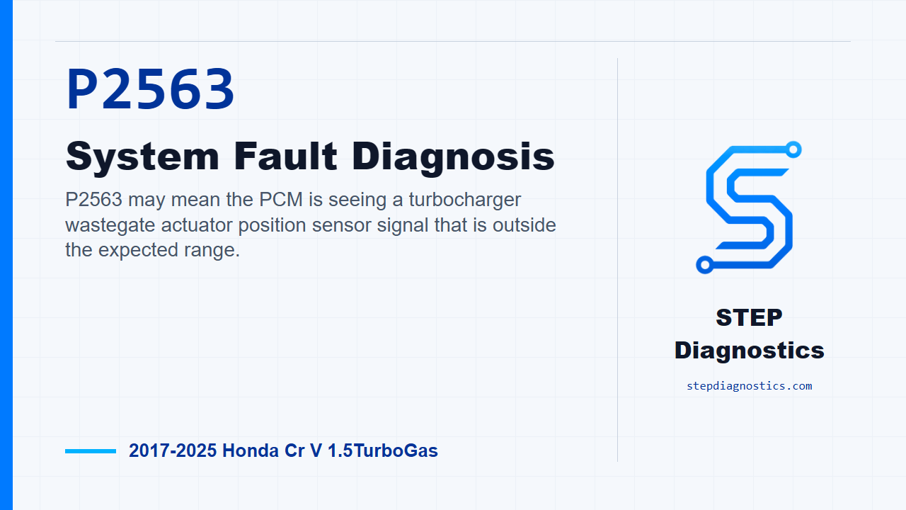
P2563 may mean the PCM is seeing a turbocharger wastegate actuator position sensor signal that is outside the expected range.
What the vehicle may do
- The vehicle may show a warning light.
- The vehicle may have reduced power or limited boost control.
- The fault may be intermittent or only stored in memory.
Possible fault areas
- Possible fault areas can include the actuator position sensor signal circuit.
- Possible fault areas can include the turbocharger connector or related wiring.
- Possible fault areas can include related PCM-side circuits.
- A PCM issue may be possible after the surrounding checks are normal.
Diagnostic path
Opening context
On this Honda CR-V with the 1.5 turbo, P2563 is pointing at the turbocharger wastegate control actuator position sensor signal. In plain shop terms, the PCM is seeing the lift sensor voltage outside the range it expects. The vehicle may have reduced boost control, poor power, warning lights, or it may only show up as a stored fault. The broad areas to keep in mind are the actuator position sensor signal, the turbocharger connector and wiring, the VCC2, DCWGL, and SG2 circuits, and, only after the rest checks normal, the PCM. Start with the basic system checks and follow a structured diagnostic approach before getting into the pinpoint tests.
Sort the fault by scan data first
The first real split in this diagnosis is the HDS data item for EWG Voltage From Lift Sensor. Look at that value and decide which side of the fault you are chasing. If it is less than 0.31 V, you are on path A. If it is more than 4.78 V, you are on path B. That scan data reading is what keeps the diagnosis from turning into random parts swapping.
Duplicate the failure
Next, reproduce the fault condition. Turn the vehicle to the ON mode and check the same HDS EWG Voltage From Lift Sensor value again. If the value is less than 0.31 V or more than 4.78 V, the failure is duplicated and you can continue with the electrical checks knowing the fault is active enough to test.
Check the sensor supply side at the turbocharger connector
From there, move to the turbocharger wastegate control actuator position sensor inspection. Disconnect the turbocharger connector, the 5P connector, then with the connector disconnected and IG mode ON, perform the unit output voltage inspection. The normal condition for that check is about 5.0 V. Since there is no direct stand-alone test for the component itself, this diagnosis works through the related components and circuits around it.
Use the jumper check to simulate the signal path
The next position sensor inspection uses the turbocharger connector again. Disconnect the turbocharger 5P connector, then jump terminals No. 3 and No. 4 with a jumper wire. Turn the vehicle to the ON mode and confirm the HDS EWG Voltage From Lift Sensor value. For this check, normal is less than 4.78 V. If that result is normal, the diagnostic path points to a problem with the turbocharger side. If it is abnormal, keep going because the fault is still in the related components or circuits.
Inspect the VCC2, DCWGL, and SG2 circuits
Before disconnecting the PCM connector, jump the SCS line with the HDS and wait more than 1 minute. Then disconnect the turbocharger 5P connector and PCM connector E, the 80P connector. With both connectors disconnected and IG mode OFF, inspect the VCC2, DCWGL, and SG2 circuits. The normal open-wire checks are less than 1 Ω for the VCC2 circuit on path A, less than 1 Ω for the DCWGL circuit on path B, and less than 1 Ω for the SG2 circuit on path B. Then inspect the DCWGL circuit for a short to ground on path A with IG mode OFF. Normal there is more than 1 MΩ. If any of those circuit checks are abnormal, the problem is in the circuit.
PCM conclusion and final takeaway
If the turbocharger-side checks and the VCC2, DCWGL, and SG2 circuit inspections all indicate normal, the remaining conclusion in this path is a PCM problem. Do not jump to that early; get there only after the sensor-side and circuit checks have passed. The takeaway for P2563 is simple: use the HDS lift sensor voltage to choose the path, duplicate the high or low signal fault, simulate the signal at the turbocharger connector, then prove the related circuits before calling the PCM. For more diagnostic training, visit stepdiagnostics.com.
Final check
P2563 is often approached as an electrical signal diagnosis: confirm the scan data, duplicate the condition, test the turbocharger connector response, and prove the related circuits before making a ƒ0
For more guided automotive diagnostics, visit STEP Diagnostics.