What the EVAP system does
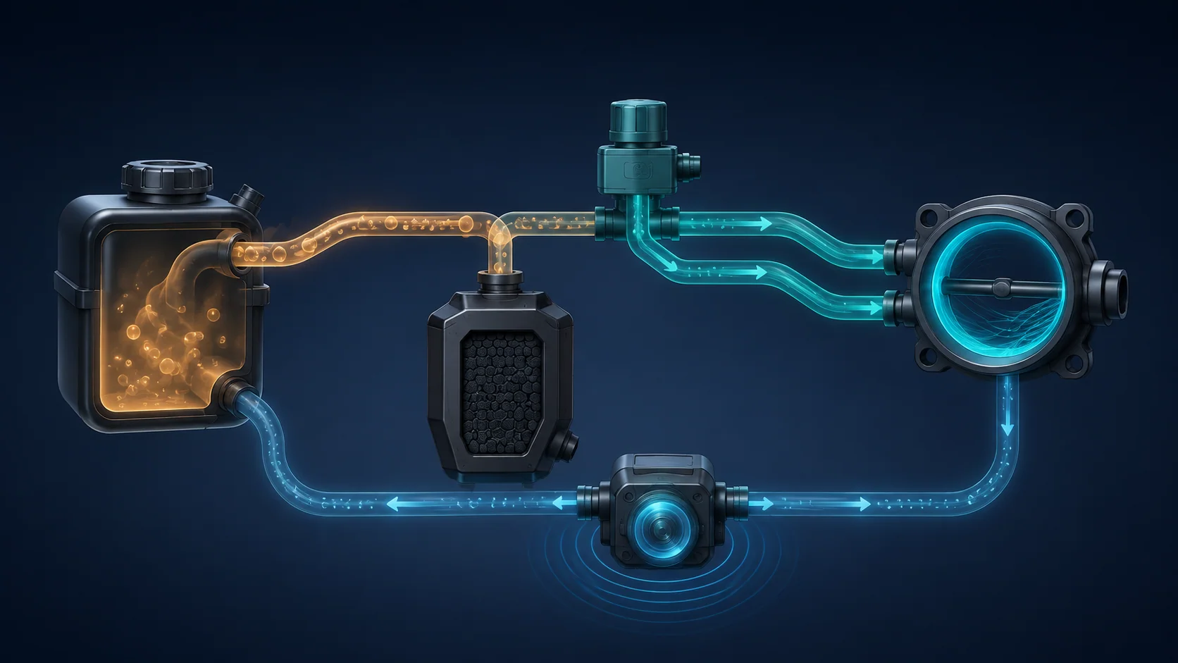
The evaporative-emissions (EVAP) system keeps gasoline vapor from venting directly to the atmosphere. It stores vapor from the fuel tank in a charcoal canister, controls when fresh air can enter the system, and meters the stored vapor into the engine so it can be burned.
Official Honda U.S. model-year references confirm that a 1.5-liter turbo gasoline CR-V configuration was offered in every model year from 2017 through 2025. Private applicability evidence confirms 4WD examples at the 2017 and 2025 endpoints; the detailed operating and diagnostic examples were verified against 2025 L15BE 4WD service information. Before applying those details to another model year or drivetrain, confirm that the exact vehicle uses the same system and procedure. Exact test conditions, scan-tool functions, pressure or vacuum limits, hose routing, component locations, and repair procedures must come from current service information for the exact vehicle being repaired.
The system has to perform two different jobs:
- During normal operation, it must manage vapor storage, fresh-air flow, and purge flow without creating an unwanted air leak into the engine.
- During self-testing, it must seal selected sections and produce the pressure response the PCM expects from a system without a leak, blockage, or control fault.
An EVAP DTC identifies a monitored behavior that failed. It does not prove that the component named in the code description should be replaced.
The main functional sections
The exact arrangement can change with model year and configuration, but diagnosis revolves around these functional sections.
- Fuel tank and filler sealing: The tank contains liquid fuel and vapor space. The filler-area flap and related seals must close correctly so the monitored system can become sealed when required.
- Vapor and purge plumbing: Pipes, tubes, hoses, joints, and seals connect the tank, canister, leak-check side, purge valve, and engine intake. A small leak, restriction, disconnection, or damaged seal anywhere in this path can change the test result.
- Charcoal canister: The canister stores fuel vapor when the engine is not purging it. It must pass air through the intended route while remaining sealed against unintended leakage.
- EVAP leak check module and fresh-air side: The leak check module helps the PCM control and evaluate the sealed system. The fresh-air path must open when the system needs ventilation and close or respond correctly during a leak check.
- EVAP canister purge valve: The PCM controls this valve to meter stored vapor toward the engine. On the turbocharged application, the valve assembly also uses one-way flow control so purge can be managed as intake pressure conditions change.
- PCM monitoring: The PCM commands valves and evaluates the resulting pressure behavior. It compares the response with the response expected for the current operating and test conditions.
How vapor storage, purge, and leak testing work together
Fuel in the tank continually produces vapor. When purge is not appropriate, the vapor is routed to the charcoal canister instead of being released. When engine conditions allow, the PCM commands the purge valve and stored vapor is drawn from the canister into the intake stream. Fresh air moves through the canister so the stored vapor can be carried toward the engine.
Because the engine is turbocharged, intake pressure is not the same in every operating state. One-way flow control in the purge-valve assembly helps prevent reverse flow and supports the intended purge route as pressure conditions change. This makes valve sealing and correct flow direction just as important as the electrical command.
For leak monitoring, the PCM needs a controlled pressure response. A sealing leak can keep the system from reaching or holding the expected response. A blockage can prevent air from moving through a route that should be open. A purge valve that leaks, sticks, or flows incorrectly can affect both normal purge operation and the leak check.
That is why an EVAP diagnosis must separate three questions:
- Can the system seal when the monitor requires it?
- Can air and vapor move through each intended route without a restriction?
- Does the commanded purge valve produce the expected pressure response without leaking when it should be closed?
What the related DTCs are telling you
| DTC | Diagnostic category | What it directs you to prove |
|---|---|---|
| P0456 | Very small EVAP leak or sealing failure | Whether the purge valve, purge path, leak-check side, filler sealing, fuel-tank side, or canister prevents the system from producing and retaining the expected leak-test response |
| P04F0 | Incorrect purge-flow response | Whether purge-valve operation, plumbing, canister flow, tank-side sealing, or the leak-check system makes the observed response differ from the commanded purge behavior |
| P04F1 | Purge flow lower than expected | Whether a valve fault, restriction, blockage, leak, damaged connection, canister problem, or tank-side condition prevents adequate purge response |
These codes overlap because they monitor the same connected vapor path. The distinction is the failed behavior: retaining a seal, producing the correct purge response, or producing enough purge response.
What the driver or technician may notice
The malfunction indicator lamp may be the only symptom. Depending on the fault, possible observations can include:
- a fuel-vapor odor, especially near a leaking connection or sealing surface;
- difficult or abnormal refueling if the tank cannot vent through the intended path;
- little or no driveability change when the fault occurs only during the EVAP self-test;
- incomplete emissions readiness after codes have been cleared.
None of these symptoms identifies the failed section by itself. A fuel odor requires an immediate safety inspection, while a purge-flow code still requires command-and-response testing.
Fuel-vapor safety comes before diagnosis
Gasoline and gasoline vapor are flammable. Work in a ventilated area away from sparks, flames, hot surfaces, and other ignition sources. Follow the approved procedure before opening any fuel or vapor connection, wear the specified personal protective equipment, and contain any fuel safely.
EVAP components and the fuel tank can be damaged by excessive pressure or vacuum. Use only the specified test equipment and the limits in current service information. Never apply unrestricted shop air, improvise a pressure source, or assume that a test limit from another vehicle applies here.
If liquid fuel leakage or a strong vapor leak is present, stop and correct the immediate hazard before running functional tests. After any repair, restore every line and connector and perform the specified leak inspection before returning the vehicle to service.
Common failure categories
1. A very small sealing leak
P0456 can result from a leak too small to find by sight alone. A missing or damaged seal, imperfect filler closure, poor pipe connection, damaged hose, leaking canister, purge-valve leakage, or leak-check-side fault can prevent the system from reaching or holding the expected pressure response.
Do not start by replacing the most familiar EVAP part. First reproduce the failed leak check, then isolate the system into sections so each normal result narrows the remaining path.
2. The purge valve does not seal or flow correctly
The purge valve must remain sealed when purge is not commanded, open enough when purge is commanded, and maintain the intended one-way behavior across changing intake conditions. A valve that sticks, leaks, or has an internal flow-control problem can create a small-leak result, an incorrect-flow result, or a low-flow result.
An electrical command alone does not prove that the valve moved or sealed. The applicable inspection must verify the valve's physical pressure and vacuum behavior.
3. The purge path is restricted, leaking, or disconnected
A pinched line, blockage, damaged hose, poor joint, or leak between the canister and purge valve can reduce the observed purge response. The same section may pass air in one direction but fail to hold vacuum when it is supposed to be sealed.
Inspect routing and recent service work, then use the exact procedure to distinguish blockage from leakage. These are different faults and require different test setups.
4. The canister or fresh-air path cannot breathe correctly
The canister must store vapor, allow intended airflow, and remain sealed against unintended leakage. Canister leakage, blockage, restriction, physical damage, or a restricted connected path can distort purge and leak-check results. A blocked path can imitate a valve or module problem even when an electrical command is present.
5. The leak-check module or its connected section is not responding
The leak check module is part of the PCM's method for controlling and evaluating the system. Before condemning it, prove the purge valve, lines, filler sealing, tank side, and canister as directed by the diagnostic sequence. The module becomes a supported conclusion only after the other branches have been tested correctly.
6. The fuel-tank or filler area does not seal
The filler-area flap, its mating surface, tank vent path, and related connections must seal for the monitor. Missing or damaged sealing surfaces, a poor connection, or leakage in the tank-side plumbing can create an EVAP fault even when the canister and purge valve are normal.
A practical diagnostic strategy
Step 1: Confirm the exact vehicle and preserve evidence
Verify model year, engine, drivetrain, and the applicable service procedure. Record confirmed and pending DTCs, freeze-frame or on-board snapshot information, readiness state, fuel level, and relevant EVAP data before clearing anything.
Step 2: Check the complete code set
Check the complete companion-code set and follow the applicable diagnostic priorities before running the EVAP isolation path. Diagnose the code combination as a hierarchy rather than treating every code as a separate parts request.
Step 3: Inspect for immediate hazards and obvious faults
Check for liquid fuel, strong vapor odor, damaged or disconnected hoses, disturbed connectors, filler-area damage, and recent repair activity. Correct an active leak hazard before commanding valves or applying test pressure or vacuum.
Step 4: Reproduce the monitored failure
Use the applicable scan-tool function or monitor conditions to confirm whether the leak check or purge-flow test currently fails. A historical code that cannot be reproduced needs careful review of stored conditions and intermittent causes before parts are removed.
Step 5: Prove the purge valve separately
Verify both command response and physical sealing or flow behavior with the specified equipment. On this turbocharged system, include the valve assembly's one-way behavior in the evaluation. Do not infer mechanical operation from a click, command status, or electrical result alone.
Step 6: Divide the EVAP path into sections
Test the purge plumbing, leak-check and fresh-air side, filler sealing, tank side, and canister in the order specified for the DTC. Isolate one section at a time and keep ports, adapters, and flow direction matched to the exact procedure.
Step 7: Match the failure type to the result
Decide whether the evidence proves leakage, blockage, insufficient flow, incorrect valve behavior, or a module conclusion reached after exclusion. Do not treat a failed pressure test and a failed vacuum-hold test as interchangeable.
Step 8: Repair and run a real verification
Restore every vapor line, seal, connector, and protective part. Perform the specified post-repair leak or purge-flow check, clear or reset only what the procedure requires, and confirm that related pending DTCs do not return. Complete the applicable monitor or readiness verification under appropriate conditions.
An erased code and a temporarily dark warning lamp are not proof of repair if the EVAP monitor has not run.
Match the repair to the proven failure
The repair may involve restoring a hose or joint, replacing a damaged seal, correcting filler-area closure, clearing a confirmed restriction, servicing the purge valve, replacing a failed canister, correcting a tank-side leak, or replacing a leak-check component after the diagnostic path supports it.
Use the result that isolated the failed section. Replacing the purge valve for every purge-flow DTC, replacing the leak check module because it appears late in a flowchart, or searching only for a loose cap on every P0456 skips the evidence the system provides.
Final takeaway
For a 2017-2025 Honda CR-V confirmed to use this 1.5 Turbo Gas EVAP configuration, diagnosis is a controlled comparison of sealing, airflow, purge-valve behavior, and pressure response. P0456, P04F0, and P04F1 overlap, but they do not ask exactly the same question.
Start with applicability and stored evidence, make the vehicle safe, reproduce the failed function, prove the purge valve, and isolate the vapor path section by section. The linked STEP DTC guides provide model-specific educational context; current service information for the exact vehicle controls every test setup, limit, component location, and repair verification.