What this code means
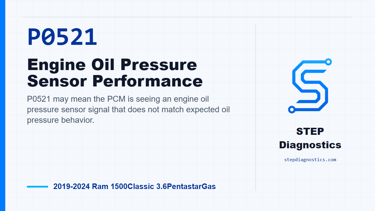
P0521 may mean the PCM is seeing an engine oil pressure sensor signal that does not match expected oil pressure behavior.
What the vehicle may do
- The MIL may illuminate.
- The vehicle may appear to run normally, or the concern may show up only under certain operating conditions.
Possible fault areas
- Possible oil level, oil condition, or lubrication concerns.
- Possible engine oil pressure sensor concern.
- Possible signal, 5-volt supply, ground, connector, or harness concern.
- Possible PCM-related concern after the rest of the diagnostic path checks out.
Diagnostic path
Open and code context
This episode is for P0521, Engine Oil Pressure Sensor Performance, on a 2019 to 2024 Ram 1500 Classic with the 3.6 Pentastar gas engine. In plain language, the PCM may be seeing an engine oil pressure signal that does not line up with the expected pressure behavior. The driver may see the MIL come on, and depending on what is actually wrong, the concern can be in the oil condition or lubrication side, the engine oil pressure sensor, the sensor circuits, connector integrity, or, after the rest of the path checks out, the PCM side of the circuit. Start with the basic system checks before getting into pinpoint testing.
Confirm the code is active or pending
First, reproduce the operating conditions for this monitor. This diagnostic runs with the engine running and engine speed above 1150 rpm. The code sets when engine oil pressure is below the calibrated specification for more than 29.8 seconds with engine speed at or above 1150 rpm. Test drive or operate the vehicle under those conditions, then use the scan tool to read and record the DTCs. If P0521 is active or pending, continue with the oil and engine checks. If it is not active or pending, treat it as an intermittent condition and follow that diagnostic path instead of forcing a conclusion.
Check mechanical and lubrication conditions first
Before blaming the sensor or wiring, check the engine mechanical and lubrication side. Look for engine mechanical tolerances out of specification, engine oil pressure out of specification, low engine oil, deteriorated or dirty oil, and oil contamination such as coolant or fuel. These checks matter because skipping them can lead to a misdiagnosis. If any of those conditions are present, repair as necessary, then verify the repair and confirm the code stays gone. If none of those conditions are present, move on to the EOP sensor operation test. And when the engine is running, stay out of line with the fan, keep hands away from pulleys, belts, and the fan, and keep loose clothing clear.
Simulate the EOP sensor signal
Next, check the Engine Oil Pressure sensor for proper operation. Turn the ignition off, disconnect the EOP sensor harness connector, then turn the ignition on. Watch EOP sensor voltage on the scan tool. Connect a jumper between the K900 sensor ground circuit and the G6 EOP signal circuit. With that jumper installed, the engine oil pressure voltage should change from approximately 4.9 volts to less than 0.1 volt. If the voltage responds within that specification, verify good pin-to-terminal contact at the sensor and PCM connectors. Then remove the EOP sensor and make sure the oil passage or port is not blocked. If connector contact and the oil passage check good, replace the EOP sensor, then verify the repair and confirm the code stays gone. If the voltage does not respond within specification, remove the jumper and continue to circuit testing.
Check the EOP signal circuit
For the circuit checks, do not probe the PCM harness connectors. That can damage the PCM terminals and create a poor terminal-to-pin connection. Use the GPEC Diagnostic Adaptor for this part of the diagnosis. Turn the ignition off, disconnect the PCM C2 harness connector, and connect Adapter, GPEC Diagnostic 10436. Measure resistance in the G6 EOP signal circuit from the EOP sensor harness connector to the GPEC adaptor. The resistance should be below 3.0 Ohms. If it is below 3.0 Ohms, continue to the 5-volt supply circuit. If it is not below 3.0 Ohms, repair the G6 EOP signal circuit for an open or high resistance, then verify the repair and confirm the code stays gone.
Check the 5-volt supply circuit
Now measure resistance in the F855 5-Volt Supply circuit from the EOP sensor harness connector to the GPEC adaptor. Again, the resistance should be below 3.0 Ohms. If it is below 3.0 Ohms, continue to the sensor ground circuit. If it is not below 3.0 Ohms, repair the F855 5-Volt Supply circuit for an open or high resistance, then verify the repair and confirm the code stays gone.
Check the sensor ground circuit
Next, measure resistance in the K900 sensor ground circuit from the EOP sensor harness connector to the GPEC adaptor. The resistance should be below 3.0 Ohms. If it is not below 3.0 Ohms, repair the K900 sensor ground circuit for an open or high resistance, then verify the repair and confirm the code stays gone. If it is below 3.0 Ohms, the main circuit resistance checks have passed, so move to connector and harness integrity.
Inspect related harness connections
Disconnect all PCM harness connectors, any related in-line harness connections if equipped, and the related component connectors. Inspect the harness and component connectors, and all male and female terminals, for connector installation problems, damaged locks, corrosion, signs of water intrusion, damaged weather seals if equipped, bent terminals, overheating from a poor connection, terminals pushed back in the connector cavity, spread terminals, and terminal tension problems. Repair any conditions you find. Then reconnect the PCM connectors, in-line connectors if equipped, and component connectors, making sure they are fully seated and the locks are fully engaged. Erase the DTCs, operate or test drive the vehicle under the monitor conditions again, and read DTCs. If P0521 does not return, the wiring or poor connection concern has been repaired. If P0521 returns after this path has checked out, replace and program the PCM using the proper programming process, then verify the repair and confirm the code stays gone.
Close
The key on P0521 is to prove the oil and mechanical side first, then prove the sensor response, then prove the signal, 5-volt supply, and ground circuits before condemning a module. Keep the verification step separate: after any repair, rerun the operating conditions and confirm the code stays gone. For more diagnostic training, visit stepdiagnostics.com.
Final check
P0521 often requires separating a real oil pressure or oil condition issue from a sensor signal or circuit issue before making a repair decision.
For more guided automotive diagnostics, visit STEP Diagnostics.