What this code means
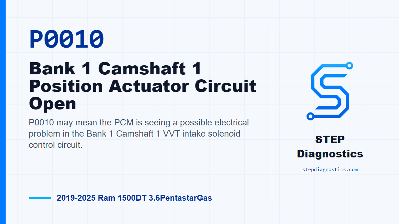
P0010 may mean the PCM is seeing a possible electrical problem in the Bank 1 Camshaft 1 VVT intake solenoid control circuit.
What the vehicle may do
- The MIL may be on.
- Stop/start can be disabled on vehicles equipped with that feature while the code is active.
- The engine may show VVT-related drivability symptoms, depending on the fault and operating conditions.
Possible fault areas
- Possible VVT intake solenoid control circuit fault.
- Possible ground circuit fault.
- Possible connector, terminal, or harness connection issue.
- Possible VVT intake solenoid issue.
- Possible software, bulletin-related, or PCM-related area after earlier checks are completed.
Diagnostic path
Open on P0010
On this Ram 1500 with the 3.6 Pentastar, P0010 points to the Bank 1 Camshaft 1 position actuator control circuit. In plain terms, the PCM may be seeing a problem in the VVT intake solenoid control side for that cam. The truck may turn the MIL on, and if it has stop/start, that system can be disabled while the code is active. Possible fault areas can include the solenoid control circuit, the ground side, connector or terminal issues, the solenoid itself, software or bulletin-related items, and PCM involvement later in the path. The monitor is simple: the engine is running, battery voltage is greater than 10.4 volts, and the PCM detects a circuit failure on the Camshaft 1/1 Position Solenoid control circuitry.
Start with the basic checks
Before chasing the circuit, complete the pre-diagnostic troubleshooting. Then check for any applicable service bulletins or PCM software updates related to this code. If there is an applicable update or repair path, handle that first and then verify the repair before going deeper into circuit testing.
Inspect the solenoid connector first
With the ignition off, check the VVT Intake Solenoid 1/1 connector before unplugging it. Make sure it was fully seated and locked. Then disconnect it and inspect for pushed-out, damaged, or spread terminals. If the connector was not locked in or the terminals are damaged, correct that condition and retest for the code before moving on.
Check the K76 control circuit for a short to another circuit
Next, isolate the Intake Solenoid K76 control circuit and check it at the PCM harness connector for a short to another circuit. Turn the ignition off, disconnect the PCM harness connector, and disconnect every component that contains that control circuit. Leave the in-line connectors connected at this point. Use the wiring diagram to follow the circuit path, connect the GPEC Diagnostic Adapter 10436 to the proper PCM harness connector, and check the isolated K76 control circuit against the other circuits at the PCM connector. With that circuit isolated, there should be no continuity between the control circuit and any other circuit. If you do find continuity, repair the short between the circuits that show continuity, using the circuit path and any in-line connectors to narrow down the location. If the flow does not return cleanly after this part of the check, pause, recheck the earlier diagnostic path, and avoid guessing.
Check the K76 control circuit for a short to ground
If the short-to-another-circuit check passes, keep the ignition off and check the K76 control circuit for a short to ground. Disconnect the intake solenoid harness connector and the PCM harness connector, then check continuity between ground and the K76 control circuit at the intake solenoid harness connector. If continuity is present, repair the K76 control circuit for a short to ground. If it is not present, continue with load testing.
Load test the K76 control circuit
Now isolate and load test the VVT Intake Solenoid 1/1 K76 control circuit for an open or high resistance. Do not load test any circuit while components are still connected to it. A good circuit should light the load test bulb bright, and that brightness should compare closely to a direct connection to battery. If the bulb is not illuminated and bright, repair the K76 control circuit for an open or high resistance. If it passes, move to the ground side.
Load test the Z904 ground circuit
For the ground circuit, disconnect the intake solenoid harness connector to isolate the ground side. Connect the positive lead of the load test tool to battery positive, and connect the negative lead to the Z904 ground circuit at the intake solenoid harness connector A. Again, the bulb should be illuminated and bright, and you compare it to a direct battery connection. To verify the circuit with certainty, perform a simple voltage drop test across the 3156 bulb in the load test tool. A 12-volt test light can be used only if it draws enough current to load the circuit. Many high-impedance test lights draw less than 0.1 amps and are not reliable for this job. The tool used for a proper load test should draw more than approximately 0.75 amps. If the ground-side load test fails, repair the Z904 ground circuit for an open or high resistance.
If the wiring tests pass, retest with the solenoid replaced
If the control circuit and ground circuit checks pass, replace the VVT Intake Solenoid 1/1 and retest for DTCs. Reconnect the intake solenoid and PCM connectors, turn the ignition on, erase the DTCs with the scan tool, then turn the ignition off for a minimum of 10.0 seconds. Turn the ignition back on, operate the vehicle under the conditions that set the code using the captured operating data, and read DTCs again. If P0010 does not return, the faulty component repaired the fault. If it does return, continue to the connection checks.
Check related PCM and component connections
If the code returns after that retest, perform any applicable bulletins, then inspect the related PCM, in-line, and component connections. Disconnect the PCM connectors, any related in-line connectors if equipped, and the related component connectors. Look for poor connector installation, damaged locks, corrosion, water intrusion, weather seal damage if equipped, bent terminals, overheating from a poor connection, pushed-back terminals, spread terminals, and poor terminal tension. Repair any conditions found. Then reconnect the PCM connectors, in-line connectors if equipped, and related component connectors, making sure every connector is fully seated and locked. Erase the DTCs, operate the vehicle under the monitored and set conditions, and read DTCs again. If P0010 does not return, the wiring or poor connection problem has been repaired. If it does return at this point, replace and program the PCM.
Verify and close
Keep verification separate from the testing steps. After any repair, verify the repair and confirm the code stays gone under the same operating conditions. The takeaway is this: P0010 is handled like an electrical circuit diagnosis first. Prove the control circuit, prove the ground, verify connector integrity, and only move to the solenoid or PCM after the earlier checks support it. For more diagnostic training, visit stepdiagnostics.com.
Final check
This code is often approached as an electrical circuit diagnosis before condemning a component.
For more guided automotive diagnostics, visit STEP Diagnostics.