Quick answer
The cooled exhaust gas recirculation (EGR) system meters a controlled amount of exhaust back into the intake so the powertrain control module (PCM) can reduce combustion temperature and nitrogen-oxide formation without sacrificing stable engine operation. P0401 describes an expected-flow response that was not detected, P0404 describes a disagreement between commanded and actual valve position, and P0405 describes an abnormally low position-signal circuit. None of these codes, by itself, identifies the failed part.
Applicability and service-information boundary
This overview applies to the 2019–2025 Ram 1500DT 3.6L Pentastar Gas configuration represented by the linked STEP guides. Detailed system-operation and diagnostic evidence was verified on the 2025 Ram 1500 Truck 4WD 3.6L eTorque MHEV application.
EGR hardware, passages, wiring, calibration, monitor conditions, scan-tool functions, component locations, cleaning methods, setup routines, and service procedures can vary by model year and equipment. Use current service information for the exact truck whenever a test requires a value, connector, command, drive condition, component location, chemical, special tool, or removal procedure.
What the EGR system does
Combustion temperature rises when the cylinder contains a large concentration of oxygen and the burn is fast and hot. The EGR system introduces a measured amount of already-burned exhaust gas into the incoming charge during selected operating conditions. That gas displaces part of the fresh charge and absorbs heat, which moderates peak combustion temperature and helps control nitrogen-oxide emissions.
The system cannot simply remain open. Too much exhaust gas at the wrong time can destabilize combustion, reduce torque, create roughness, or contribute to stalling. Too little flow can prevent the emissions strategy from achieving its target. The PCM therefore decides when EGR is appropriate, commands a valve position, watches the position feedback, and evaluates whether the engine responds as expected.
How the controlled valve and feedback loop work
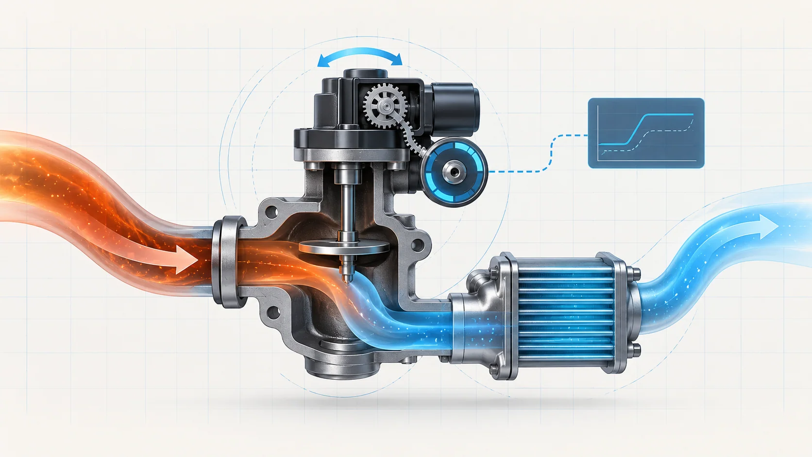
On the exact 2025 source application, the cooled EGR valve assembly combines an electric actuator, gear reduction, a valve mechanism, a return-to-closed spring, and an integral position sensor. The PCM drives the actuator in both directions and manages the electrical duty needed to move and hold the valve. The spring provides a closing bias if control is lost.
The position sensor gives the PCM feedback about valve movement. In control-system terms, the PCM has both a request and a reported result:
- It calculates the EGR flow needed for the current operating condition.
- It commands the valve toward a target position.
- It compares actual position feedback with the desired position.
- It evaluates engine response to decide whether commanded movement produced believable EGR flow.
This distinction is central to diagnosis. A valve can move electrically but still fail to produce the expected gas flow because a passage is restricted or the system leaks. Conversely, gas passages can be clear while a signal, reference, ground, connector, actuator, or internal mechanism prevents accurate position control.
What the related DTCs tell you
| DTC | Diagnostic category | What it directs you to prove |
|---|---|---|
| P0401 | EGR system-flow performance | Whether commanded EGR activity produces the expected engine response, and whether restriction, leakage, carbon, the valve assembly, or related electrical faults explain the missing response |
| P0404 | Commanded-versus-actual position performance | Whether the valve follows the PCM request and whether supply integrity, sticking, actuator stress, position feedback, connections, or the assembly explain the disagreement |
| P0405 | Position-signal circuit low | Whether a grounded or cross-shorted signal path, connector or terminal problem, sensor fault, wiring fault, or controller-side condition is forcing an implausibly low signal |
The code identifies the evidence path that failed. It does not choose the replacement part.
What the driver or technician may notice
- a malfunction indicator lamp with little or no obvious drivability complaint;
- roughness, hesitation, reduced response, unstable idle, or stalling if the valve is open or flowing at the wrong time;
- pinging or elevated combustion-temperature symptoms when expected EGR flow is absent under a relevant load condition;
- multiple EGR position, control, reference-voltage, or performance codes rather than one isolated DTC;
- a code that appears only during a specific warm driving condition and cannot be reproduced immediately in the bay;
- evidence of soot near an EGR joint, suggesting leakage, or heavy deposits in the valve and passages;
- a previous EGR repair followed by a related code because required setup or verification was incomplete.
These observations are clues, not proof. Preserve the complete scan and stored operating data before clearing codes.
Common failure categories
Restricted gas flow or carbon accumulation
Deposits can restrict a passage, coat the valve stem or seat, or prevent the valve from reaching or holding the requested position. The PCM may see movement without the expected engine response, or it may see the actual position lag the request. Deposit evidence should lead to a root-cause review as well as the applicable cleaning or replacement decision; air, fuel, oil-consumption, or combustion problems can accelerate soot formation.
Do not assume that every performance code means a dirty valve. Prove that the gas path is restricted or that the mechanism is sticking according to the current service procedure.
Leakage in the EGR path
An EGR joint, tube, cooler connection, valve interface, or other boundary can leak. A leak can reduce delivered flow, leave visible soot, change the relationship between commanded position and engine response, or introduce hot exhaust where it does not belong.
Inspect the complete accessible path with the system cool. Soot at a connection is useful evidence, but the exact leak test and repair procedure belong to service information for the truck being repaired.
Valve actuator or mechanical movement faults
The motor, gear mechanism, valve shaft, spring, or internal assembly can bind, overheat, wear, or fail. A mechanically stuck valve may create both position and flow evidence. An electrical command reaching the assembly does not prove that the valve moved through its usable range, and a scan-tool position value does not by itself prove that exhaust actually flowed.
Compare the request, feedback, and engine response rather than judging the actuator from sound or one snapshot.
Position-sensor, reference, signal, ground, wiring, or terminal faults
The position feedback depends on a stable reference, signal path, sensor ground, connector fit, and terminal integrity. A short to ground, short between circuits, open or high-resistance connection, spread terminal, corrosion, water intrusion, pushed-back terminal, harness damage, or internal sensor problem can create false position evidence.
Inspect first, then isolate the circuit with the exact approved procedure. Do not probe sealed or controller terminals in a way that can create the fault you are trying to find.
Calibration, setup, or controller-side conditions
Software level, learned valve position, and required post-repair setup can affect how the PCM interprets the assembly. A cleaning or replacement that is not followed by the applicable setup routine may leave misleading position evidence. Controller replacement belongs at the end of a service-information decision tree after the actuator, sensor, circuits, terminals, software, and setup have been addressed.
A practical system-first diagnostic strategy
1. Preserve evidence and confirm applicability
Confirm the exact year, engine, emissions configuration, software applicability, and current service information. Save the full module scan, confirmed and pending DTCs, freeze-frame or failure-record data, EGR desired and actual position where available, fuel-trim information, coolant temperature, load, and recent repair history before clearing anything.
2. Establish code priority
Separate circuit evidence from performance evidence. If an active position-signal, reference, ground, actuator-control, or related electrical DTC is present, diagnose it before trusting EGR position or flow conclusions. P0401 should not outrank a fault that makes the valve command or feedback unreliable.
3. Inspect the system cold
Allow the exhaust and EGR hardware to cool. Inspect connectors, locks, terminals, harness routing, heat protection, visible joints, mounting surfaces, tubes, cooler connections, and recently disturbed areas. Look for soot, broken retainers, corrosion, water intrusion, heat damage, chafing, or deposits supported by the applicable inspection procedure.
4. Compare desired position, actual position, and engine response
Use a capable scan tool and the applicable procedure. A useful test separates three questions:
- Did the PCM request movement?
- Did position feedback follow the request plausibly?
- Did the engine data respond as expected when the valve moved?
If the request changes but feedback does not, focus on control, supply, feedback, wiring, terminals, sticking, or the assembly. If feedback follows but the engine response is missing, focus on gas-path restriction, leakage, false feedback, or another engine condition that distorts the expected response.
5. Prove circuits without damaging them
For a low-signal DTC, determine whether the signal is being pulled toward ground, shorted to another circuit, lost through a terminal problem, or generated incorrectly by the sensor. Use the specified breakout method, fused jumper, meter loading, connector handling, and controller-protection precautions only when the exact service procedure calls for them.
Voltage present with a connector unplugged does not prove the circuit can operate correctly under all conditions. Likewise, a forced signal response may prove part of the input path without proving the valve assembly or gas path.
6. Inspect for restriction, leakage, and sticking
After electrical integrity is credible, use the applicable inspection and functional steps to determine whether the valve and passages are restricted, leaking, or mechanically sticking. Avoid forcing the valve or introducing unapproved cleaners, pressure, or tools. If deposits are found, investigate conditions that could cause excessive soot rather than treating cleaning as the complete diagnosis.
7. Choose the repair category only after localization
The supported repair may be a connector or harness repair, leak repair, passage service, approved cleaning, valve-assembly replacement, software update, required setup, or—only after the specified isolation—controller repair or replacement. Match the repair to the failed section rather than the code label.
8. Complete setup and verify the repair
Reconnect every connector and retainer, restore heat protection and routing, and perform any required EGR-valve setup or learned-position routine. Reproduce the stored operating region or run the current verification procedure. Confirm that desired and actual positions remain plausible, the expected engine response returns, and no related pending or confirmed DTC resets.
A cleared warning lamp without the monitor or verification routine completing is not a verified repair.
Safety around the EGR system
EGR components carry hot exhaust and can remain hot after shutdown. Allow sufficient cooling time, wear appropriate eye and hand protection, and keep wiring, tools, chemicals, and flammable material away from hot surfaces. Exhaust gas is hazardous; use effective ventilation and exhaust extraction whenever the engine must run indoors.
Running tests place the technician near fans, belts, hot surfaces, and moving driveline parts. Secure leads and tools, place the transmission in the specified state, apply the parking brake, and follow current service information before any test that could start or move the truck. Do not open a hot cooling-system connection or disturb a cooled-EGR component until the applicable pressure and temperature precautions are satisfied.
Final takeaway
On the 2019–2025 Ram 1500DT 3.6L Pentastar Gas, EGR diagnosis is a closed-loop problem: the PCM requests valve movement, the position sensor reports what the assembly did, and engine data shows whether useful exhaust flow actually occurred. P0401, P0404, and P0405 describe three different breaks in that evidence chain—flow response, position performance, and signal-circuit integrity.
Preserve the operating evidence, give electrical faults priority, compare desired position with actual position and engine response, inspect the gas path for restriction or leakage, localize the failed section, and complete the required setup and verification. The linked STEP guides provide model-specific educational paths; current service information for the exact truck controls specifications, commands, connectors, service procedures, and final verification.