Quick answer
The diesel aftertreatment system filters soot, creates controlled heat for regeneration, meters diesel exhaust fluid (DEF), and uses selective catalytic reduction (SCR) to reduce nitrogen oxides. DPF pressure, temperature, DEF pressure, NOx-sensor, regeneration, and catalyst-efficiency codes describe different failed evidence paths. None of them proves by itself that the DPF, reductant pump, NOx sensor, or SCR catalyst should be replaced.
Applicability and service-information boundary
This overview applies to the 2020–2025 Chevrolet Silverado 2500 6.6L Diesel vehicle group represented by the linked STEP guides. Detailed system-operation and diagnostic evidence was verified on the exact 2022 Chevrolet Silverado 2500 4WD 6.6L turbo-diesel application, with target-range applicability corroborated by the retained L5P Silverado HD sources.
Component arrangements, calibrations, connector details, scan-tool functions, monitor conditions, temperature and pressure limits, and service procedures can vary. Use current service information for the exact VIN, model year, engine, emissions configuration, and installed hardware whenever a test requires a value, command, connector view, component location, reset, regeneration, or repair procedure.
A truck arrives with an emissions warning and a customer asking whether it needs a new DPF. The useful first question is which part of the system has failed its monitor. A regeneration-frequency code, a low differential-pressure code and a downstream NOx-sensor performance code describe different problems, even when the dashboard message sounds similar.
This overview explains how to separate those problems and choose the next diagnostic direction. It covers the 2020-2025 Silverado 2500 with the 6.6-liter Duramax diesel, commonly identified as the Silverado 2500HD. Component arrangements, calibrations and test conditions vary: use service information matched to the truck's VIN, model year and engine for every measurement, command and repair.
DPF, DEF and SCR: three different jobs
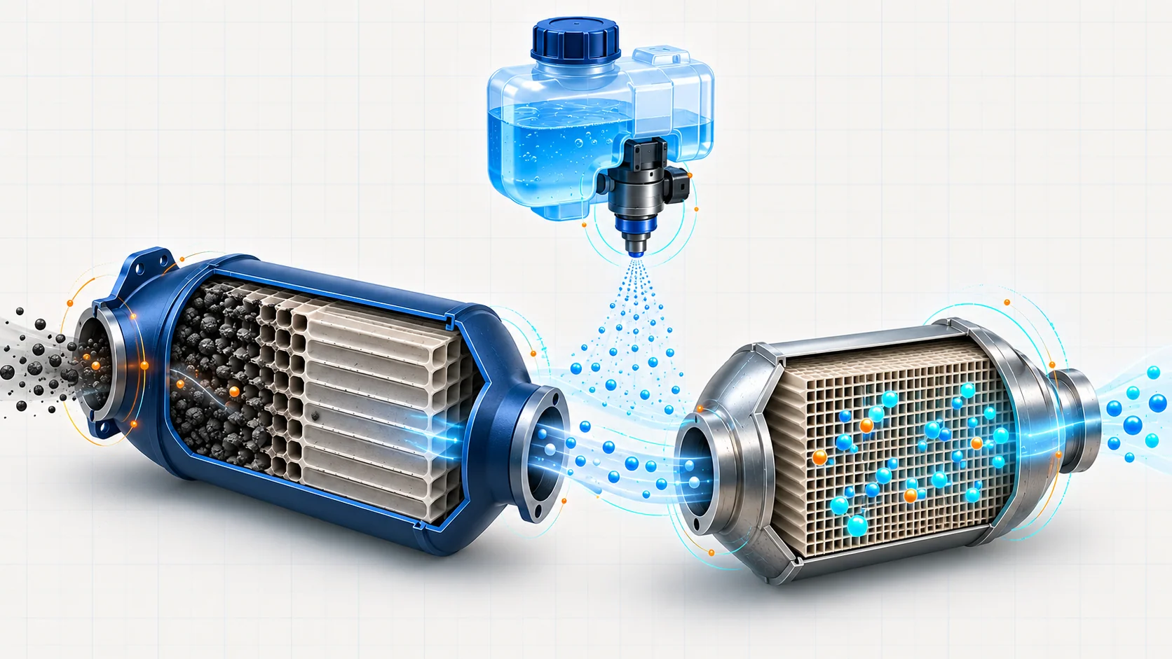
The diesel particulate filter, or DPF, captures soot in a porous filter. Regeneration raises exhaust temperature so accumulated soot can be oxidized. The engine controller evaluates soot loading and operating conditions; the filter's pressure signal is one input, not a direct measurement of everything inside it.
DEF is diesel exhaust fluid, the urea-and-water reductant supplied to the exhaust dosing system. Its reservoir, pump, heaters, pressure feedback and injector support controlled delivery. Having fluid in the tank does not establish that pressure feedback is accurate or that the correct amount reaches the exhaust.
The SCR catalyst uses reductant-derived ammonia to help reduce nitrogen oxides, or NOx. NOx sensors and exhaust-temperature information help the controller evaluate operation. A reading taken before the relevant sensors and exhaust system are ready cannot answer the same question as data recorded under the specified diagnostic conditions.
Diesel oxidation catalysts, or DOCs, also participate in exhaust treatment and heat management. The reviewed L5P service description includes more than one oxidation-catalyst stage. Think in terms of functions before assuming that a generic diesel exhaust diagram represents this truck's exact layout.
A particularly useful distinction is exhaust fuel dosing versus DEF dosing. Hydrocarbon fuel dosing helps generate heat for DPF regeneration; DEF dosing supports SCR chemistry. A problem with one is not automatically a problem with the other.
Use the DTC to choose a diagnostic direction
Read the complete code set and failure records before clearing anything. Related electrical, temperature or pressure faults can affect the inputs used by an aftertreatment monitor. Start with the prerequisites specified by the applicable procedure.
| Code and STEP guide | Diagnostic direction | What the code does not establish |
|---|---|---|
| P2002: DPF efficiency | Determine why the filter is not producing the expected soot-reduction evidence. | That the filter substrate is the only possible cause. |
| P2452: DPF pressure-sensor circuit | Establish whether the pressure-signal circuit is credible before using it to judge loading or flow. | That pressure across the filter has actually failed a mechanical limit. |
| P244A: Low differential pressure | Check the pressure signal, sensing hoses and exhaust integrity before judging the filter. | That low indicated pressure means a clean, intact DPF. |
| P2463: Soot accumulation | Determine whether soot loading is credible and why normal regeneration did not keep it within the expected range. | That a forced regeneration or filter replacement is automatically safe or sufficient. |
| P2459: Regeneration frequency | Investigate why regeneration is occurring too frequently, including operating history and relevant system faults. | That the DPF must be replaced. |
| P24A0: Regeneration temperature control low | Evaluate why commanded regeneration heat is not being achieved or controlled as expected. | That adding more regeneration attempts will correct the underlying cause. |
| P200C: DPF high temperature | Follow the excessive-temperature diagnostic path and evaluate the relevant inputs and heat source. | That another commanded regeneration is the right next step. |
| P20E8: Reductant pressure low | Determine why the reductant system cannot establish the expected delivery pressure. | That the tank level or pump alone explains the fault. |
| P204B: Reductant pressure feedback performance | Separate a feedback problem from a delivery-pressure problem using the specified tests. | That adding DEF or replacing the pump will resolve the fault. |
| P20EE: SCR NOx catalyst efficiency | Establish whether valid operating conditions, dosing, sensing, exhaust integrity, and catalyst performance support the efficiency conclusion. | That the catalyst is defective from one code or one data snapshot. |
| P2201: NOx sensor 1 performance | Evaluate upstream NOx sensing under the conditions required by the code-specific procedure. | That upstream NOx concentration alone identifies the failed component. |
| P229F: NOx sensor 2 performance | Evaluate the downstream NOx-sensor diagnostic conditions and related faults. | That the sensor or SCR catalyst has been proven defective. |
The linked guides organize each code's diagnostic path. The service procedure for the vehicle being repaired controls test order, enabling conditions and pass/fail criteria.
Why a pressure reading can mislead you
DPF differential pressure reflects the pressure difference across the filter under the conditions at that moment. Exhaust flow matters, as does the integrity of the sensing system. Comparing an idle reading with an unrelated loaded reading can hide the reason the values differ.
For a low-pressure code such as P244A, inspect the sensing hoses and their connections for damage, disconnection, leaks, kinks or restrictions. Check the relevant exhaust path and sensor inputs as directed. A disconnected pressure path can make the reported value misleading; replacing the filter would leave that cause in place.
A useful record includes the operating condition as well as the number: engine state, relevant temperatures, pressure behavior and any active input faults. Compare those observations with the specified reference conditions. Avoid adopting a pressure threshold from another engine or model year.
Soot and ash also need to be separated. Regeneration burns soot; it does not remove noncombustible ash. Ash accumulation requires the applicable service assessment. It is not a reason to prescribe cleaning or replacement from mileage alone.
Frequent regeneration is a symptom to explain
Repeated regeneration can prompt a shop to focus entirely on the filter. First establish the operating history: short trips, extended low-load use and interrupted events provide context for why the system may struggle to complete its normal process.
Then examine the conditions that support regeneration. The controller needs credible pressure and temperature information and a system capable of managing exhaust heat. A monitor or sensor fault may change which tests are appropriate. An active excessive-temperature condition deserves its own diagnosis before any attempt to create more heat.
Exhaust leaks deserve attention on this engine family. GM bulletin 23-NA-061 identifies leaks as a possible contributor to several L5P emissions complaints, including regeneration-frequency faults. It also explains why a smoke-only inspection can miss a leak. No visible smoke is not, by itself, proof that the exhaust is sealed.
Use the bulletin and service information applicable to the truck for the actual leak-test method and interpretation. Do not improvise test pressure, block components based on a general article, or assume every trace of leakage has the same significance.
Separate DEF delivery from NOx conversion
When reductant pressure feedback is the diagnostic direction, organize the evidence around three questions: is the reported pressure credible, can the system produce the required delivery condition, and are the control and electrical prerequisites satisfied?
Fluid level answers only part of that investigation. Temperature, heater operation, pump control, pressure feedback and dosing conditions can matter. Cold-weather thawing and shutdown purge behavior are controlled processes; do not interpret a snapshot without checking the system's current operating state.
For a NOx-sensor performance code, verify the conditions that make the signal meaningful. The L5P description uses NOx sensing before and after SCR, with sensor warm-up and communication requirements. A comparison made at cold idle is not a universal SCR efficiency test.
Use the code-specific procedure to separate sensor operation from conditions elsewhere in the system. Exhaust integrity and related faults may affect the investigation. Condemning the catalyst from a single downstream reading skips the question of whether the test conditions and inputs were valid.
A practical intake-to-verification workflow
1. Preserve the complaint and failure conditions
Record the customer's exact warning and when it appeared. Ask about the duty cycle, recent DEF filling, prior emissions repairs and whether regeneration was interrupted. Save the full code set and available failure records before clearing them.
These details guide the investigation; they are not proof of a cause. A recent refill, for example, does not establish a fluid-quality fault.
2. Check prerequisites before commanding a test
Confirm the truck's identity and consult current service information and applicable bulletins. Resolve prerequisite faults in the order specified by the diagnostic procedure. Inspect accessible wiring, connectors, sensing hoses and exhaust components without assuming that the highest-cost part is the starting point.
Group the evidence into pressure sensing, heat and regeneration, reductant delivery, or NOx-sensor performance. When codes span several groups, follow their documented dependencies.
3. Test under the prescribed conditions
Record commanded and observed behavior where the procedure provides a comparison. Include operating state and relevant temperatures alongside scan data. Use exact connector references, limits and service-tool commands only from information applicable to this vehicle.
A failed check should lead to the next supported branch. Repeating a regeneration command is not a substitute for finding why the previous event failed or why it was not permitted.
4. Match the repair to the demonstrated fault
The repair may involve wiring, a pressure-sensing hose, an exhaust leak, a dosing-system component, a sensor or a filter-related service. Choose it from the diagnostic evidence. Follow the specified programming, setup, cleaning or replacement requirements for that repair.
Reset soot, ash or learned values only when the applicable procedure requires it after the corresponding work. Changing a stored value does not change the physical condition of the exhaust system.
5. Verify the original failure path
Use the prescribed post-repair verification procedure and confirm that the relevant system can operate under the required conditions. Recheck the original complaint, repaired connections and associated faults.
Clearing codes alone does not demonstrate a repair. Document what was tested and what completed. If the required monitor or verification conditions were not reached, record that limitation instead of describing the truck as fully verified.
Treat service regeneration as a hot-exhaust operation
A commanded service regeneration can produce hazardous exhaust temperatures. The reviewed GM procedure requires an outdoor location, clearance from people and combustible materials, and continuous attendance. An ordinary shop exhaust-extraction hose is not suitable for that event.
Use the exact vehicle procedure for preparation, permitted conditions, supervision and abort criteria. Address disqualifying faults first. Do not turn a general overview into authorization to force regeneration on a truck with an unresolved high-temperature or other prerequisite fault.
Choose the next guide from the evidence
For filter efficiency, loading, and pressure questions, continue with P2002 DPF efficiency, P2452 pressure-sensor circuit, P244A low differential pressure, or P2463 soot accumulation. For regeneration concerns, use P2459 regeneration frequency, P24A0 low temperature-control limit, or P200C high temperature.
For the reductant and NOx side, start with P20E8 low reductant pressure, P204B pressure feedback, P20EE SCR efficiency, P2201 NOx sensor 1 performance, or P229F NOx sensor 2 performance. The goal is a testable diagnostic direction, followed by a repair whose result can be checked.