Applicability basis: Official GM model-year information and verified vehicle-configuration records confirm the 6.6-liter diesel in the Silverado HD throughout the 2020-2025 model-year range. Detailed diagnostic and service evidence was verified for a 2022 Silverado 2500 4WD with the 6.6-liter turbo-diesel V8. Exact connector locations, signal specifications, scan-tool commands, learn prerequisites, mechanical timing procedures, and repair instructions must come from service information for the vehicle being repaired.
What the engine timing and position system does
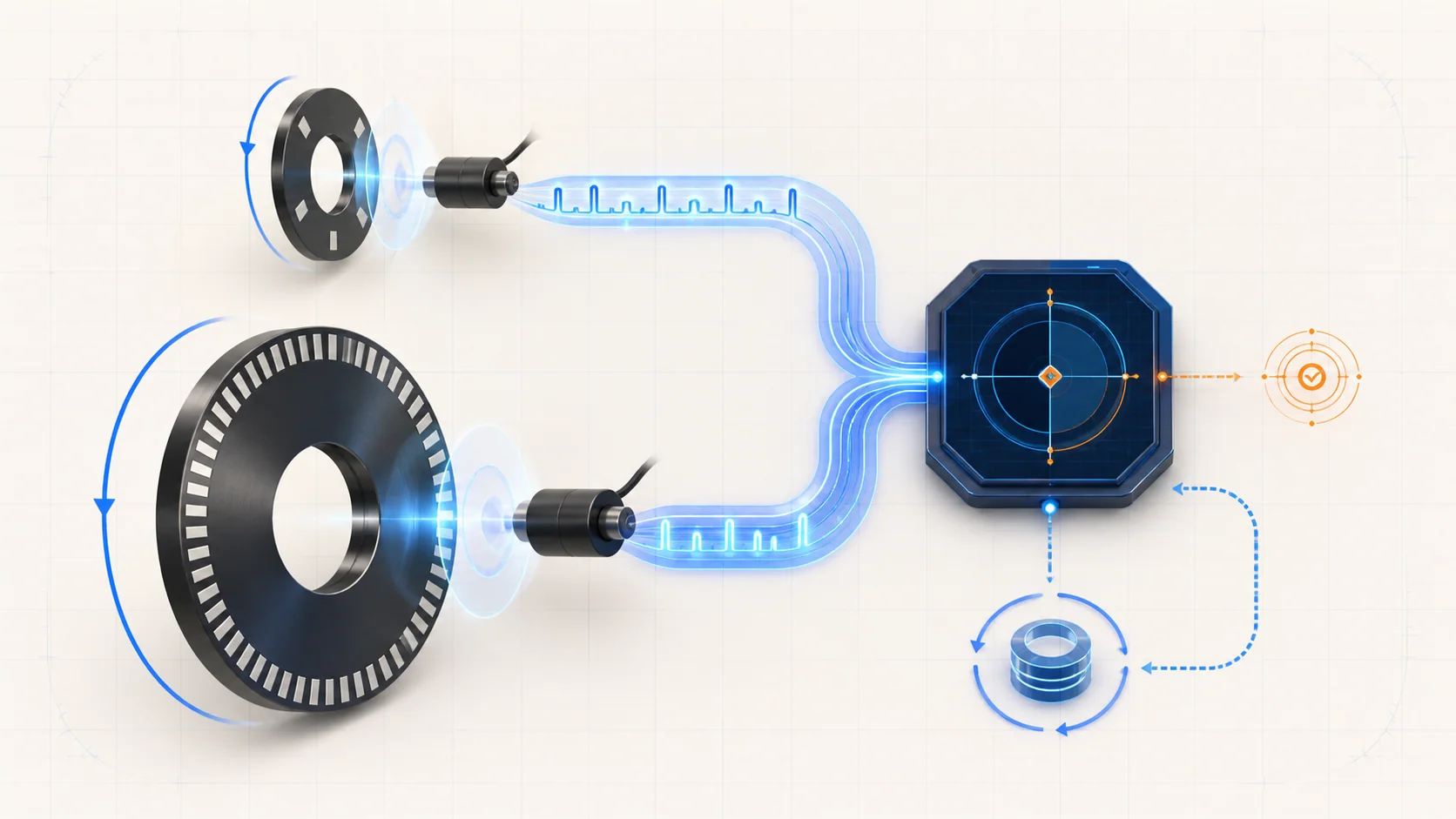
The engine control module needs a reliable answer to three basic questions: how fast is the crankshaft turning, where is the crankshaft in its rotation, and how is the camshaft positioned relative to it? The crankshaft position sensor, camshaft position sensor, their rotating targets, and the mechanical relationship between the crankshaft and camshaft provide that information.
On this system, the sensors react to changing magnetic conditions as target features pass them. Their electronics convert those changes into repeating signals. The control module interprets the signal frequency and pattern rather than simply looking for voltage at a connector.
The two inputs have related but different jobs:
- The crankshaft position signal provides the detailed rotational reference used to determine engine speed and crankshaft position.
- The camshaft position signal identifies camshaft position so the control module can establish the expected crank-to-cam relationship.
- The control module compares both patterns to determine whether they are present, stable, synchronized, and mechanically plausible.
- A separate crankshaft-position variation learn stores compensation for small manufacturing and installation tolerances so the control module can recognize changes associated with misfire more accurately.
A DTC identifies which monitored behavior failed. It does not identify the failed part by itself.
The main functional sections
- Crankshaft position sensor and circuit: The sensor, reference supply, low-reference path, signal circuit, connector, harness, and control-module input must all work as a complete channel.
- Crankshaft target or reluctor: The rotating target creates the repeating pattern and reference feature the sensor reads. Damage, movement, contamination, incorrect alignment, or excess play can alter the pattern even when the electrical circuit tests normally.
- Camshaft position sensor and circuit: This channel also depends on a sensor, reference and low-reference paths, signal circuit, connectors, wiring, and control-module input.
- Camshaft target or exciter: Its physical relationship to the camshaft must remain correct. A loose, damaged, misaligned, or contaminated target can create missing or implausible cam information.
- Mechanical crank-to-cam relationship: Gears, shafts, targets, installation, and related timing hardware must preserve the intended relationship. Mechanical movement can create a correlation fault without causing a simple open- or short-circuit DTC.
- Engine control module logic: The module evaluates signal presence, pattern, synchronization, correlation, and learned crankshaft variation. A module is one possible endpoint of a directed diagnostic path, not the first assumption.
How the control module interprets the signals
Signal presence is the first layer. If the control module cannot detect a usable crankshaft signal, engine-speed and position information becomes unreliable. If it cannot detect a usable camshaft signal, it loses the expected cam reference. These are circuit and signal-presence questions.
Signal quality is the second layer. A crankshaft signal may still be present but contain an irregular pattern, lose synchronization, or disagree with the expected reference pattern. This is why P0335 and P0336 should not be treated as duplicate names for the same test.
Correlation is the third layer. The crankshaft and camshaft signals can each appear electrically active while their relationship is outside the expected window. P0016 therefore opens a broader diagnostic category: sensor installation, target alignment, mechanical timing, excess play, or another condition that shifts one signal relative to the other.
The variation learn is a fourth and separate layer. It stores compensation for small variations in the crankshaft-position reference periods. That compensation helps the control module distinguish normal variation from the subtle speed changes used in misfire detection. It does not move a target, correct mechanical timing, restore a missing sensor signal, or repair wiring.
What the related DTCs are telling you
| DTC | Diagnostic category | What it directs you to prove |
|---|---|---|
| P0016 | Crankshaft-to-camshaft correlation implausible | Whether related CKP/CMP faults are primary, both signals are credible, sensor and target installation is correct, and the mechanical crank-to-cam relationship is intact |
| P0315 | Crankshaft-position variation not learned | Whether the required learned value is absent and whether the exact learn prerequisites and procedure can be completed and retained |
| P0335 | Crankshaft-position signal missing or unusable | Whether the CKP reference, low-reference, signal circuit, connector, sensor, or control-module input explains loss of the signal; use companion performance or correlation evidence before moving to target or timing checks |
| P0336 | Crankshaft-position pattern or synchronization performance | Whether an intermittent circuit, sensor, target, excess play, contamination, or mechanical condition makes the CKP pattern irregular or causes synchronization loss |
| P0340 | Camshaft-position circuit signal missing or unusable | Whether the CMP reference, low-reference, signal circuit, connector, sensor, or control-module input explains loss of the signal; use companion performance or correlation evidence before moving to target or timing checks |
The code combination changes the order of work. A shared reference-voltage fault can affect more than one sensor. A CKP or CMP signal DTC can make a correlation result secondary. P0315 may be expected after certain repairs or module events, but it should not be used to explain away an active electrical or mechanical fault.
What the driver or technician may notice
Possible observations include:
- a malfunction indicator lamp with few other symptoms;
- extended cranking or an intermittent hard start;
- a crank-no-start condition when a critical position signal is unavailable;
- stumble, rough running, stall, or inconsistent operation if a signal drops out while the engine is running;
- a fault that appears only with heat, vibration, harness movement, or conditions similar to the stored failure record;
- reduced misfire-detection accuracy when the crankshaft variation value is not learned;
- several reference, CKP, CMP, correlation, or misfire-related codes that must be diagnosed in priority order.
None of these observations proves that a sensor, control module, or mechanical timing component has failed. The same symptom can originate in other engine, fuel, electrical, or starting-system faults.
Safety comes before signal diagnosis
Running tests may place the technician near belts, pulleys, the cooling fan, hot engine parts, and moving linkages. Keep hands, clothing, test leads, and tools secured away from rotating components. Remember that an electric fan can start unexpectedly, including when the engine is not running.
Turn the vehicle off and allow the required module power-down time before disconnecting sensors or control-module connectors when the service procedure directs it. Do not back-probe, jumper, or load a circuit unless the exact procedure identifies the correct terminals, tool, and method. An improvised jumper can damage a sensor or control-module driver.
A crankshaft-position variation learn is a controlled service routine, not a casual throttle test. It requires a fully charged battery and the exact enable conditions specified for the truck. Secure the vehicle, keep the work area clear, follow every scan-tool prompt and the applicable OEM procedure, and stop if the vehicle state, engine behavior, warning message, or shop environment makes the routine unsafe.
Mechanical timing or target service can require substantial disassembly, single-use fasteners, and careful reassembly of disturbed air, electrical, and fluid connections. Use current service information and verify every disturbed connection before starting the engine.
Failure categories represented by these DTCs
1. Shared reference or circuit integrity is lost
An open circuit, excessive resistance, short to ground, short to voltage, spread terminal, corrosion, chafed harness, poor connector retention, or shared reference fault can remove or distort a position signal. Diagnose shared supply faults before deciding that two sensors failed at the same time.
2. A signal is present only intermittently
Heat, vibration, harness movement, oil or debris intrusion, terminal tension, or internal sensor failure can make a signal disappear briefly. Stored failure records, active and resynchronization counters, and a controlled harness-movement check can help connect the fault to the condition without replacing parts on suspicion.
3. The sensor cannot read the target correctly
Incorrect sensor seating, physical damage, foreign material, an unsuitable air gap, target damage, or movement between the target and shaft can change the signal. A clean electrical test does not prove the mechanical signal source is correct.
4. Mechanical correlation has shifted
Incorrect installation, looseness, wear, excess play, or damage in the crank-to-cam drive and target relationship can shift the signals relative to each other. Correlation diagnosis belongs after related signal and circuit faults are understood, because a missing or corrupted input cannot support a reliable mechanical conclusion.
5. The learned variation value is missing
The control module may lack a completed crankshaft-position variation learn after relevant service or a memory/module event. Complete the learn only after the engine-position system is credible and all prerequisites are met. If the learn will not complete or remain stored, follow the exact P0315 path rather than repeating the routine indefinitely.
A practical diagnostic strategy
Step 1: Confirm the exact application and preserve evidence
Verify model year, engine, drivetrain, installed modules, software context, and the applicable service procedure. Save confirmed, pending, and history DTCs along with the failure record or freeze-frame data before clearing anything. Note engine speed, synchronization status, active or resynchronization counters, battery condition, and any recent sensor, engine, battery, or control-module work.
Step 2: Classify and prioritize the code set
Separate the concern into shared reference, missing CKP, irregular CKP, missing CMP, crank/cam correlation, and variation-not-learned categories. Follow the related-code priorities in the service procedure. Resolve shared reference and direct signal faults before judging P0016, and resolve active signal or mechanical faults before attempting a variation learn.
Step 3: Inspect before disturbing the system
With the engine safe and off, inspect accessible CKP and CMP harness routing, connectors, retainers, heat exposure, chafe points, contamination, recent service areas, sensor seating, and grounds or shared circuits identified by the wiring information. Avoid disconnecting an intermittent connection until its condition and position are documented.
Step 4: Use scan data to test signal behavior
Check whether the applicable active counters increment, whether synchronization is established, and whether resynchronization events occur. Reproduce the stored conditions when it is safe. A harness-movement test is useful only when performed carefully while the relevant parameter is being watched and all leads and hands are kept clear of moving parts.
Step 5: Prove the circuit before condemning the sensor
Use the correct wiring diagram, breakout method, and specified test tools for the exact vehicle. Verify the reference, low-reference, and signal paths under the conditions directed by the procedure. A correct supply reading at one moment does not rule out terminal tension, an intermittent open, or a signal that fails under vibration.
Step 6: Inspect the sensor-to-target relationship
If the circuit can carry a credible signal, evaluate sensor installation, mounting, target condition and alignment, contamination, and mechanical play using the applicable procedure. Do not use a generic target drawing or tooth count to authorize disassembly; the exact service information controls access and inspection criteria.
Step 7: Separate correlation from learn status
For P0016, confirm that both inputs are credible before judging their relationship, then follow the mechanical timing and target checks supported by the procedure. For P0315, confirm the system is otherwise healthy, satisfy every prerequisite, and perform the prescribed variation learn. A successful relearn does not validate mechanical timing, and a failed relearn does not automatically condemn the control module.
Step 8: Verify the complete repair
After the repair, reconnect and secure every disturbed circuit, air connection, shield, retainer, and mechanical fastener. Complete any required setup or learn procedure. Reproduce the relevant operating region, confirm the signal and synchronization data remain stable, check that no related pending DTC returns, and verify that the monitor has had a valid opportunity to run.
Clearing codes or seeing a warning light remain off before the monitor runs is not repair verification.
Match the repair to the proven failure
The supported repair may be a terminal or harness repair, restored reference or low-reference circuit, corrected connector retention, properly installed sensor, removed contamination, repaired or replaced target, corrected mechanical timing component, completed variation learn, sensor replacement, or—only after the directed branches support it—a control-module repair or replacement with the required programming and setup.
Avoid three common shortcuts: replacing the CKP sensor for every P0335 or P0336, replacing the CMP sensor for every P0340, and performing a variation learn to hide an unresolved P0016. Each shortcut skips the distinction the monitors are designed to provide.
Final takeaway
On the 2020-2025 Chevrolet Silverado 2500 6.6 Diesel, engine-position diagnosis is a layered evaluation of circuit integrity, signal presence, signal pattern, crank-to-cam correlation, mechanical target relationship, and learned crankshaft variation.
Start with the complete code set and stored evidence, resolve shared reference and direct signal faults, prove the circuits, then inspect sensor installation, targets, and mechanical correlation. Treat the variation learn as a final controlled setup procedure when it is required—not as a repair for a bad signal or shifted timing. The linked STEP DTC guides provide model-specific educational context; the exact service information for the truck being repaired controls specifications, commands, disassembly, and verification.