Engine position sensing gives the powertrain control module (PCM) a reference for engine rotation and cylinder phase. On the Ford F-150 5.0 Coyote gas engine, a crankshaft or camshaft position code identifies a signal concern to investigate. It does not, by itself, prove that a sensor has failed or that mechanical timing is incorrect.
This educational introduction covers STEP's 2015–2025 F-150 5.0 Coyote Gas library. Early and late configuration checks support that model-and-engine scope, not identical sensors, wiring or diagnostic procedures across the range. Match the actual year, engine, drivetrain and calibration before choosing service information. Exact sensor identification, locations, connector terminals, electrical limits and repair procedures remain vehicle-specific.
Purpose and operation
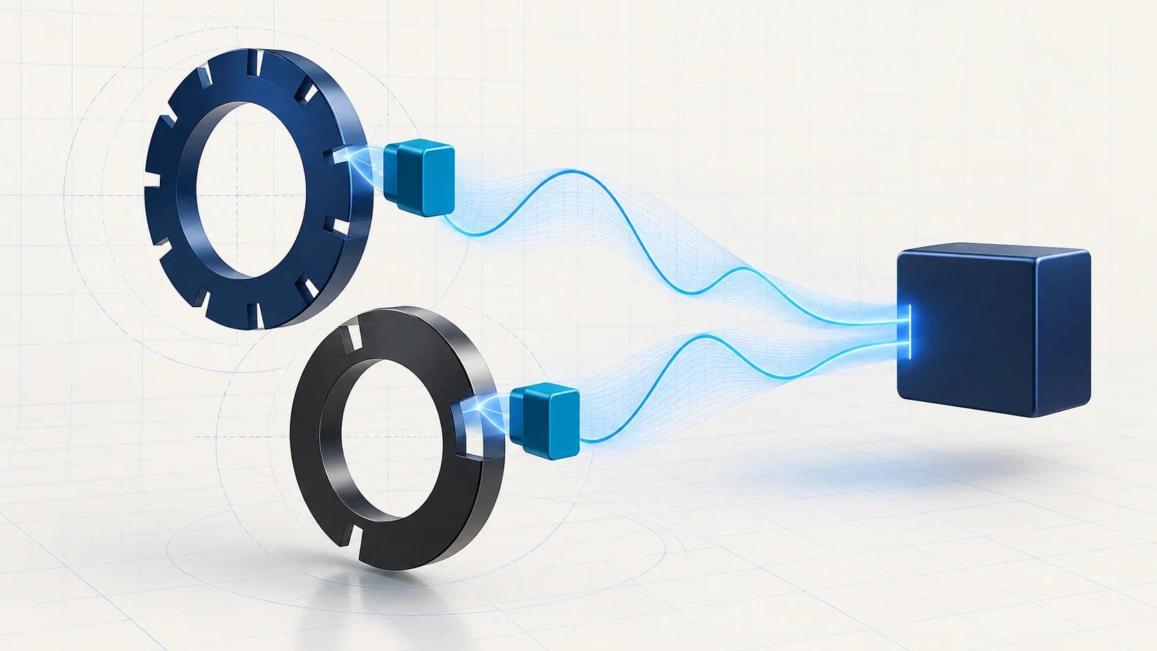
The crankshaft position (CKP) input tells the controller about crankshaft position and rotational speed. A rotating reference wheel and its sensor create the information the controller interprets. The camshaft position (CMP) input adds phase information so the controller can distinguish where a cylinder is in its operating cycle.
The late-endpoint engine description explains that the PCM uses CKP information to calculate a spark target and CMP information to synchronize individual coil firing with the compression stroke. These are related inputs, but they are not interchangeable. Seeing engine-speed data does not establish that the cam signal is correct, and a cam signal does not prove that the crank input is reliable under all conditions.
Think of the system as a physical rotating reference, a sensor and signal circuit, and controller interpretation. A problem at any of those layers can undermine usable position information. This overview does not specify sensor count, pulse-wheel geometry or whether a particular circuit uses one electrical sensor technology rather than another.
How the related DTC guides fit
P0335 — Crankshaft Position Signal Performance introduces the crank-signal path. In the early-endpoint diagnostic description, the concern involves an expected CKP pulse that is missing under calibrated operating conditions. Keep the complete code and the actual vehicle's diagnostic definition; do not assume that every year or subtype uses identical detection logic.
P0340 Diagnostic Guide introduces a monitored camshaft-position signal concern. The early-endpoint source directs the technician to the applicable component information for physical identification. A bank or channel label must not become a guessed connector, sensor location or interchangeable part.
Use these guides to organize the investigation, then confirm the exact source target before applying a test. Shared diagnostic material can contain branches for different sensor technologies or configurations. Do not combine values from one branch with terminals from another. No exact pin assignments or test thresholds from those guides are generalized here.
Failure categories and symptoms
Separate electrical, installation and physical-reference concerns. An open, short or intermittent terminal connection can interrupt usable input. Sensor damage or incorrect installation can also matter. The rotating reference and, where the applicable diagnostic path indicates it, cam timing or trigger alignment deserve their own investigation rather than automatic sensor replacement.
Signal interference is another category. Harness routing, alterations or damaged shielding can affect a cam signal intermittently. Treat these as supported possibilities to check, not proof that any nearby electrical device is the cause. A controller-side concern needs supporting results after the correct inputs and connections have been evaluated.
The complaint may include an illuminated malfunction indicator lamp, a cranks-but-will-not-start condition, intermittent starting, stalling or rough running. Those symptoms have other possible causes. An inactive crank input can prevent starting, but a no-start complaint alone does not identify which component or circuit has failed.
A practical diagnostic strategy
Preserve all relevant codes, their full descriptions and available environmental data before erasing anything. Record whether the concern occurs during starting, after warm-up or intermittently. Review other codes and recent repairs so that the diagnostic starting point reflects the whole case rather than only the first sensor named by the scanner.
For a cranking complaint, establish battery and starting-system condition before interpreting engine-speed data. Compare the observed cranking behavior with the scan information using the applicable procedure. Missing or implausible speed data is evidence to investigate the input path; it is not a sensor replacement instruction by itself.
Inspect accessible harnesses, connector seating, terminal condition and evidence of disturbed installation. If access or inspection of the sensor and reference wheel is required, follow the vehicle-specific service procedure. An electrical test cannot certify mechanical alignment, and a visual inspection cannot prove that an intermittent signal remains sound while the engine operates.
Use the identified circuit's prescribed test sequence and suitable adapters. Voltage checks require the correct meter mode, reference point and operating state. Resistance checks require the specified power-off and isolation conditions. A generic resistance specification is not a valid test for every sensor design. Do not apply external voltage to a signal circuit or invent a missing probe location.
Where the procedure calls for signal capture or synchronization data, use the correct connection method and compare the result with an applicable known-good reference. A waveform from another engine, year or sensor technology is not automatically a valid standard. Keep electrical signal quality distinct from a conclusion about mechanical cam-to-crank timing.
Repair categories and verification
Repair the demonstrated fault: wiring or terminals, installation, a sensor supported by tests, or a confirmed physical-reference or timing concern. Controller work belongs only in the applicable diagnostic path, with its installation and programming requirements. Do not substitute a module or a pair of sensors simply because the evidence is incomplete.
After repair, confirm that disturbed connectors and harness routing are restored correctly. Carry out the required self-test and any configuration-specific learning or verification procedure only when the source calls for it. Do not prescribe a universal reset or relearn across the whole catalog range.
Recheck the original symptom, codes and relevant position information under safe, applicable conditions. Save the post-repair results alongside the original evidence. Clearing a code or achieving one successful start does not by itself prove that an intermittent fault is resolved.
Safety and scope
Prevent unintended starting and follow the applicable isolation procedure before working near rotating components or disconnecting circuits. If a test requires cranking, secure the vehicle and keep hands, tools and leads clear of moving parts. Use the prescribed fuel or ignition disabling procedure when required; this overview provides no universal fuse-removal recipe.
Let hot components cool and use approved support for any work underneath the truck. Avoid damaging controller terminals with unsuitable probes. If there is evidence of a serious mechanical timing problem, do not keep cranking or running the engine simply to reproduce a code. The goal is reliable position information and a verified repair, not repeated fault erasure.