What this code means
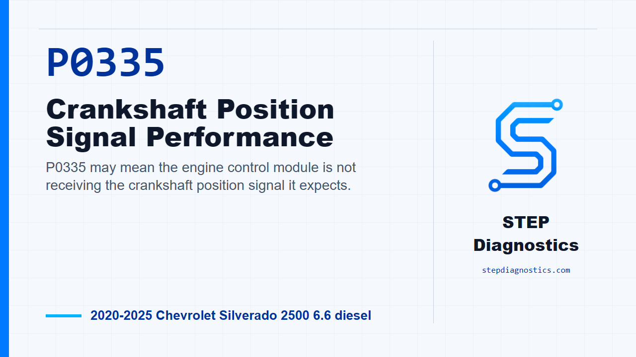
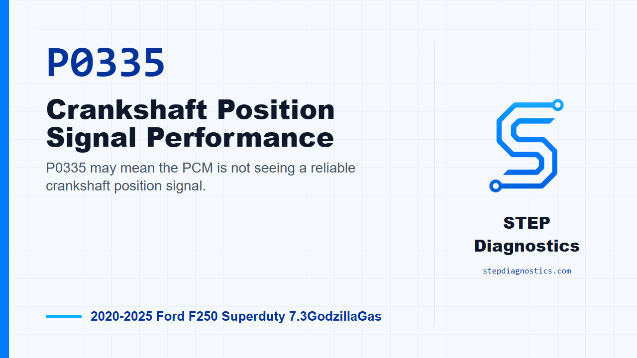
P0335 may mean the PCM is not seeing a reliable crankshaft position signal.
What the vehicle may do
- The vehicle may have a hard start or long crank.
- The vehicle may crank and not start.
- The engine can sometimes run poorly if the crank signal is erratic.
Possible fault areas
- Possible CKP sensor circuitry concern.
- Possible crankshaft pulse wheel concern.
- Possible CKP sensor concern.
- Possible PCM involvement.
Diagnostic path
Opening context
On this 2020 to 2025 F-250 Super Duty with the 7.3 gas engine, P0335 is a crankshaft position signal code. In plain language, the PCM may not be seeing a clean, reliable crank signal when the engine is cranking or running. The truck may have a hard start, long crank, or no-start condition. The broad fault areas can include the CKP circuit, the crankshaft pulse wheel, the CKP sensor, or, less often, the PCM. If other codes are present, check what they mean first, then stay focused on the crank signal path for this code.
Start with the basic system checks
Before testing the crank signal, make sure the battery is fully charged and the starting system is working correctly. This test depends on a valid cranking event. Normal engine cranking speed is between 150 RPM and 350 RPM, and the engine should crank for greater than 3 seconds while attempting to start.
Check RPM during cranking
Disable the fuel pump by removing the fuel pump fuse. Turn the ignition on, access the PCM data, and monitor the RPM PID while cranking the engine. For P0335, a value of 0 revolutions per minute ( RPM ) indicates a CKP concern. Another P0335 condition says it the same way: a value of 0 RPM indicates a CKP concern. If the RPM is greater than 150, continue with the crank sensor and trigger wheel inspection. If there is no usable RPM signal, still continue into the CKP diagnostic path unless the engine cranks less than 3 seconds with no RPM signal.
Short crank with no RPM signal
If the engine cranks less than 3 seconds with no RPM signal, do not guess at the CKP sensor yet. That result sends you toward base engine and cam timing checks first: verify base engine timing, make sure the camshaft sensor trigger wheels are not damaged, and confirm the camshafts are rotating while the engine is cranking. Repair as necessary, clear the PCM DTCs, and repeat the self-test.
Inspect the sensor and trigger wheel
Next, turn the ignition off and look for obvious physical problems at the CKP sensor and trigger wheel. Check the trigger wheel for contamination or debris, and inspect both the sensor and wheel for damage. A trigger wheel that is physically damaged, bent more than 1.0 mm, or contaminated on the magnetic surfaces may cause an intermittent CKP signal. If you find a concern here, repair as necessary, reset the keep alive memory, and carry out the Misfire Monitor Neutral Profile Correction with the scan tool.
Check CKP bias voltage and sensor resistance
When the diagnostic path moves into the PCM-side CKP checks, disconnect the CKP sensor connector, turn the ignition on, and check for correct CKP bias voltage. The decision point is whether the voltage is between 1 V - 3 V. If the voltage is in that range, turn the ignition off and check CKP sensor resistance. The sensor resistance decision point is whether the resistance is between 250 Ω - 1100 Ω. If the resistance is not in range, the repair decision is a new Crankshaft Position sensor, followed by keep alive memory reset and Misfire Monitor Neutral Profile Correction. If the terminal locations for either of these checks are not clear at the vehicle, stop and verify the connector identification before testing. Do not guess on terminal locations.
Check shield ground and CKP circuit integrity
Next, keep the ignition off, disconnect the PCM connector, and check the CKP harness shield ground. The CKP harness shield is built into the harness around the CKP circuits to help protect the signal from outside electrical noise, and that shield is grounded internally through the PCM. Measure between the CKP shield in the harness and the PCM connector terminal, and look for resistance less than 5 ohms. After that, check for a short between CKP positive and CKP negative; the resistance should be greater than 10000 Ω. Then check the CKP circuits for an open; the resistance should be less than 5 Ω. Then check for a short to ground; the resistance should be greater than 10000 Ω. Finally, turn the ignition on and check the CKP circuit for a short to voltage. If voltage is present where it should not be, repair the short circuit, clear the PCM DTCs, and repeat the self-test. If the lead locations for these checks are not clear at the vehicle, pause and verify the connector information before putting a meter lead on the circuit.
Check voltage at the CKP sensor
On the sensor voltage side of the path, turn the ignition off and disconnect the CKP sensor connector. Turn the ignition on and measure voltage between C101 Pin 1 and C101 Pin 2. You are looking for between 4.5 V - 5.5 V. If that voltage is not in range, pause this CKP path and continue the appropriate circuit diagnostic instead of condemning the sensor. If the voltage is in range, keep going with the circuit integrity checks.
Check the CKP signal circuit for an open
Turn the ignition off and disconnect the PCM connector. Measure resistance between C101 Pin 3 and C175E Pin 99. The resistance should be less than 5 Ω. If it is not, repair the open circuit, clear the PCM DTCs, and repeat the self-test. If it passes, continue to the short-between-circuits check.
Check for shorts between circuits and to voltage
Next, check for a short between circuits at the listed CKP connector points. The resistance should be greater than 10000 Ω. If it is not, repair the short circuit, clear the PCM DTCs, and repeat the self-test. Then turn the ignition on and check the CKP circuit for a short to voltage. If any voltage is present where it should not be, repair the short circuit, clear the PCM DTCs, and repeat the self-test. If the pin information for these checks is not clear at the vehicle, stop and verify the connector identification before testing. Do not guess on terminal locations.
Look for intermittent harness damage
If the hard circuit checks pass, turn the ignition off, reconnect the PCM connector, and inspect for an intermittent harness problem. Look closely for chafed CKP or CMP wiring and any physical damage around those harnesses. Chafed wiring or harness damage may create an intermittent short in the CKP or CMP circuit. If you find a concern, repair as necessary, clear the PCM DTCs, and repeat the self-test. If you do not find anything, continue to the connector seating check.
Connector seating and final decision point
For the final check, turn the ignition off, disconnect the PCM connector and CKP sensor connector, and inspect for pushed out pins and corrosion. Reconnect the PCM connectors and the CKP sensor connector, and make sure they are seated correctly. Then verify whether the concern is still present. If it is still present and this is a crank no-start, pause this flow and continue the no-start diagnostic path. If the concern is still present for the other P0335 conditions covered here, install a new Crankshaft Position sensor, reset the keep alive memory, and carry out the Misfire Monitor Neutral Profile Correction with the scan tool. If the concern is gone, the system is operating correctly at this time, and the issue may have been caused by a loose or corroded connector.
Verify the repair
Keep verification separate from testing. After a circuit repair, clear the PCM DTCs and repeat the self-test. After keep alive memory reset and Misfire Monitor Neutral Profile Correction, complete those steps with the scan tool, then confirm the code stays gone and the starting complaint is resolved. The takeaway is simple: prove the crank signal, inspect the wheel and connector condition, and let the circuit results make the repair decision. For more diagnostic training, visit stepdiagnostics.com.
Final check
P0335 diagnosis often starts by proving the crank RPM signal, then checking sensor condition, wheel condition, connector condition, and circuit integrity before making a repair decision.
For more guided automotive diagnostics, visit STEP Diagnostics.