A hard start, a long crank or an engine-position code does not automatically identify a failed sensor. The PCM needs usable crankshaft and camshaft information, and the fault can lie in the sensing element, its electrical path, the physical target or the conditions under which the information is being evaluated.
This educational overview covers the 2020–2025 Ford F250 Superduty 7.3L Godzilla gasoline family. Detailed diagnostic evidence was checked on the exact 2020 and 2025 F-250 4WD 7.3L gasoline configurations. Those endpoints support a conceptual family overview; they do not prove identical sensors, wiring, calibrations or test procedures for every intervening truck. Use the service information applicable to the exact vehicle for component identification, connector views, meter endpoints, limits and repair instructions.
What crankshaft and camshaft signals do
The crankshaft position sensor, or CKP, gives the controller information about crankshaft rotation. The camshaft position sensor, or CMP, provides a camshaft reference. These related inputs help the PCM establish engine-position information, but they remain distinct signal paths with different tests.
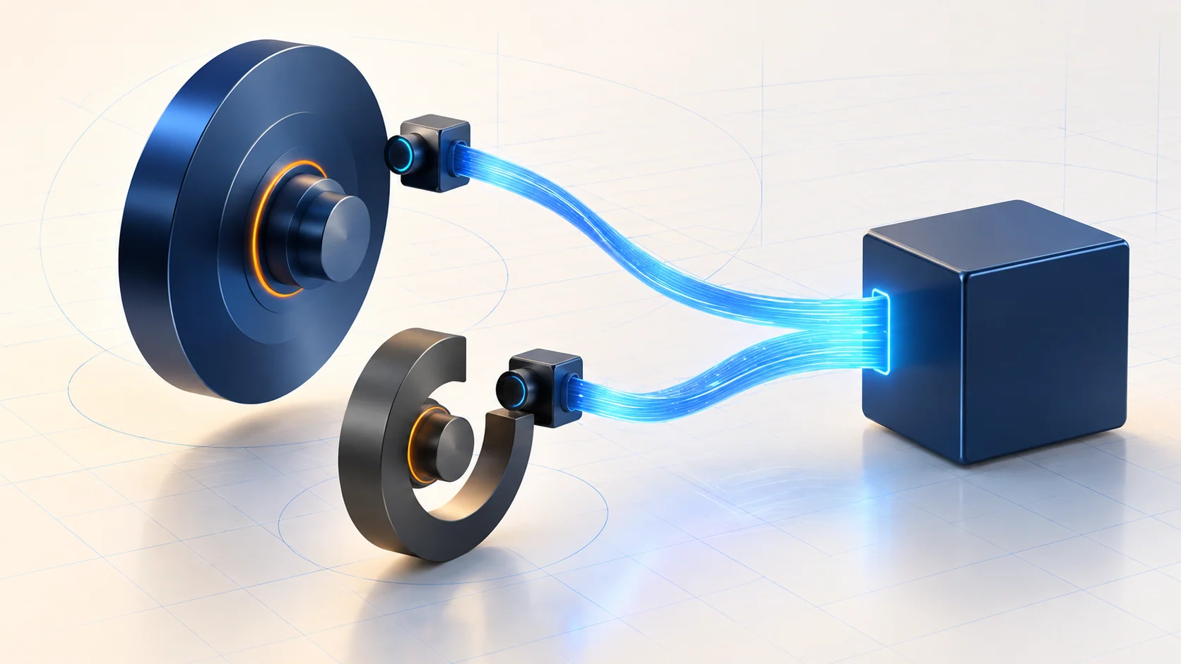
A useful conceptual chain is the rotating target, the sensor reading it, the harness and connections, and the PCM interpreting the signal. A problem anywhere along that chain can affect the information available to the controller. The physical target matters as well as the electrical circuit: the verified CKP procedures include inspection for trigger-wheel damage, contamination and debris.
RPM and synchronization observations should not be treated as interchangeable. RPM reports engine-speed information; the applicable synchronization observation evaluates another aspect of the position-signal relationship. Seeing an RPM value does not establish that both signal paths and their relationship are correct. Conversely, no reported RPM during a poorly controlled cranking test is not a complete diagnosis of the sensor itself.
Two guides, two diagnostic starting points
| STEP guide | What it directs attention toward | What it does not prove |
|---|---|---|
| P0335 — Crankshaft Position Signal Performance | A missing, unreliable or otherwise faulted crankshaft-position signal path, interpreted with the full code and complaint. | That a new CKP sensor will repair every occurrence. |
| P0340 — P0340 Diagnostic Guide | The camshaft-position input and its electrical or synchronization diagnostic path. | That base-engine timing, a camshaft actuator or the PCM has failed. |
The verified late CKP document distinguishes several subtypes within the P0335 family, including an intermittent-signal category. Record the complete code, including any subtype, rather than flattening every result into one generic sensor fault. The published links cover the vehicle family; confirm exact applicability before following their detailed steps.
Symptoms and failure categories
The CKP guide discusses hard starting, extended cranking and crank-without-start complaints. Erratic signal information can also accompany poor running. The CMP guide includes no-start and cam-synchronization or drivability concerns. These symptoms help reproduce the complaint, but they do not identify the failed part or prove that one fault explains every symptom.
Electrical categories include opens, shorts, connector damage, poor terminal contact and problems with the required signal or supply path. The shared source procedures cover different circuit arrangements. Do not select a sensor resistance test, bias-voltage check or supply test simply because it appears somewhere in the same document; its application and branch must match the truck.
Routing, shielding, harness alterations and interference form another useful category. Both verified CMP paths include harness inspection, and the shared diagnostic flow includes a generator-noise branch. This is a reason to follow the specified checks when directed, not a reason to condemn the alternator or disconnect it as an improvised experiment.
Physical inspection can reveal a damaged sensor or crankshaft target. Mechanical timing checks are a separate, conditional branch in the CKP diagnostic flow. Neither a stored position code nor the broad title of a shared camshaft-timing document proves a mechanical timing defect. Controller-side conclusions belong after the relevant inputs, circuits and connections have been evaluated.
A practical diagnostic strategy
- Identify the vehicle and preserve the evidence. Record the complete code set, available fault context and the exact complaint before clearing anything. Separate an active no-start from an intermittent stored-code concern, and note whether the fault occurs during starting or running.
- Make the cranking test meaningful. The verified early CKP procedure requires a charged battery and a functioning starting system. Use the specified test setup and cranking conditions. Starting performance and test duration can change the branch; a casual glance at the RPM display is insufficient.
- Read each observation for its actual purpose. Use engine-speed and synchronization information only under the conditions the applicable test specifies. A live-data result can guide the next check without proving sensor integrity, target condition and mechanical timing all at once.
- Follow the electrical path and inspect its environment. Check the correct circuits and connectors, including routing or interference where directed. Connected, disconnected and isolated resistance measurements are different setups. Never substitute an assumed ground point or carry a limit from one configuration into another.
- Inspect the sensing target or mechanical branch when directed. Use the prescribed access and inspection procedure. An observed physical defect supports a repair decision; the code alone does not. If the selected test passes, return to the relevant symptom or code flow instead of forcing a sensor replacement.
Scope testing can be useful where the applicable diagnostic procedure and equipment support it. This overview supplies no universal waveform, tooth pattern, phase angle, pinout or pass/fail limit. Do not treat the conceptual illustration as a diagnostic trace or component-location diagram.
Repair categories, safety and verification
Repairs may restore a damaged circuit or terminal, correct a routing problem, replace a proven faulty sensor, or address an established target or mechanical concern. A module repair and any required programming remain procedure-directed decisions. Some CKP repair branches specify additional reset or learning work; confirm which operations the exact repair requires instead of clearing codes and assuming the job is finished.
Secure the truck against movement and keep hands, clothing and test leads away from rotating parts. Use ventilation for running tests and allow hot components to cool before access. Follow the specified starting, ignition and fuel-system precautions for any test that requires cranking without starting. Do not improvise disabling methods, jumper connections or energized resistance checks.
After repair, restore every disturbed connection and complete the specified clearing, reset or learning steps where required. Repeat the relevant self-test and safely reproduce the original complaint conditions. Verify that the expected signal observations and symptoms have recovered. An intermittent concern may need testing under its original conditions; clearing the warning lamp alone does not establish a completed repair.