Applicability basis: Vehicle records confirm the Civic Sedan with the 2.0L K20C2 engine at both the 2016 and 2024 endpoints. The detailed procedures used for this overview were collected from the exact 2024 Honda Civic Sedan L4-2.0L (K20C2) target. Component revisions, monitor conditions, scan-tool commands, connectors, and specifications must still be confirmed for the exact vehicle being repaired.
What the EVAP system does
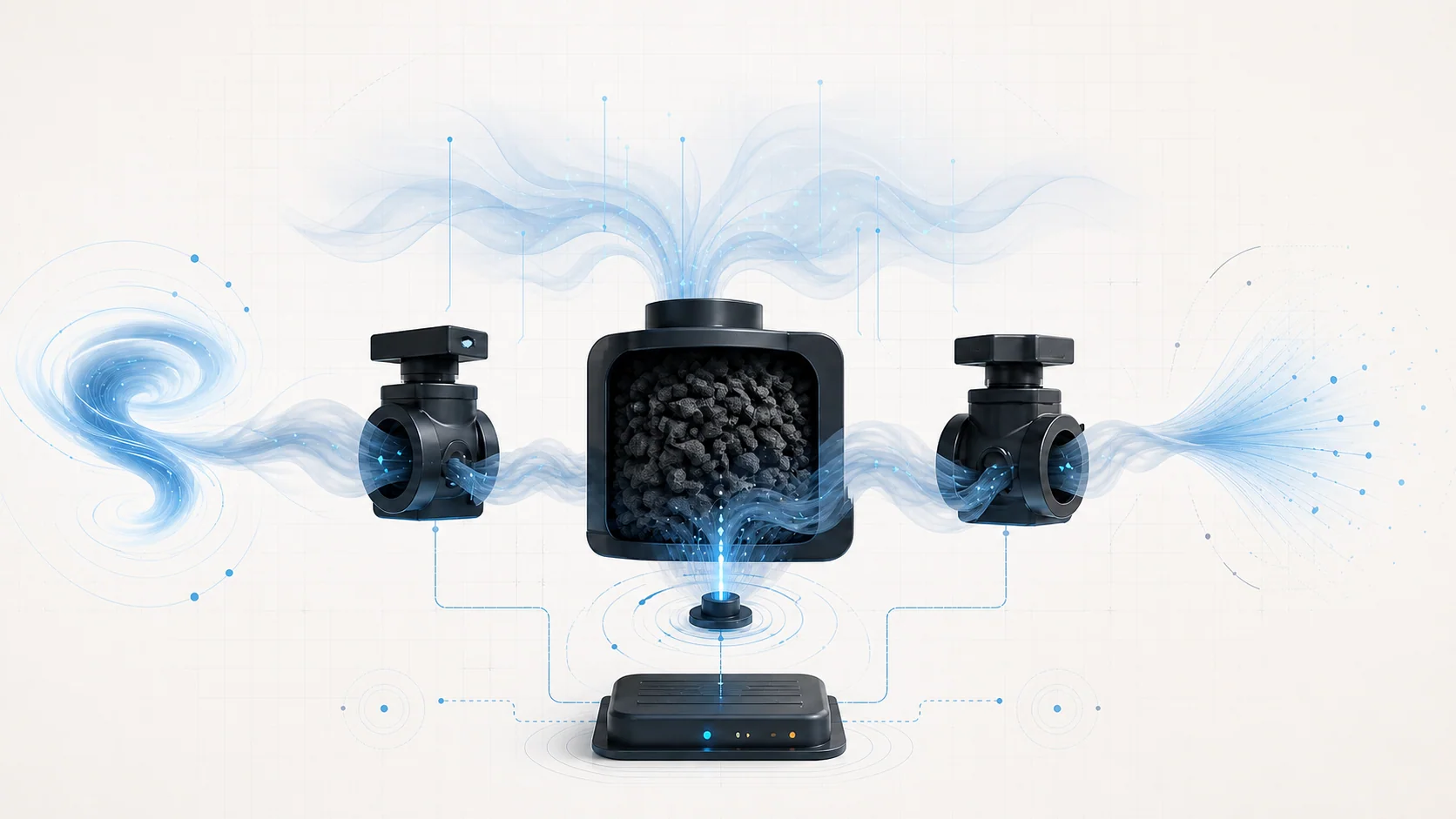
The evaporative emission control system, or EVAP system, prevents gasoline vapor from being released directly into the atmosphere. Fuel vapor produced in the tank is routed to a charcoal canister for temporary storage. When engine and operating conditions are suitable, the powertrain control module (PCM) meters that stored vapor into the intake so it can be burned.
That description sounds simple, but diagnosis depends on four separate abilities:
- The system must contain vapor without an unintended leak.
- The purge path must move vapor toward the engine at a controlled rate.
- The vent path must admit fresh air during normal operation and close when the PCM needs to test the system.
- The fuel tank pressure (FTP) sensor must report a believable pressure or vacuum response.
An EVAP DTC reports which expected behavior failed. It does not automatically identify the part that caused the failure.
The main components on this Civic
The exact layout and service access points can vary within the model range. Confirm them in service information for the vehicle being repaired. The 2024 K20C2 diagnostic sources center on these components:
- Fuel tank and filler assembly: The tank, filler path, vapor-recirculation path, seals, shut-off features, and related joints form part of the vapor boundary.
- EVAP canister: Activated charcoal stores vapor until the engine can purge it.
- EVAP canister purge valve: The PCM varies this valve to meter vapor from the canister into the intake.
- EVAP canister vent shut valve: This valve is normally open so outside air can pass through the canister. The PCM can close it when the system must be sealed for a monitor or test.
- Fuel tank pressure sensor: The FTP sensor lets the PCM observe pressure and vacuum changes during purge, vent, and leak checks.
- Hoses, tubes, ports, seals, and O-rings: A small sealing loss, disconnected line, pinched hose, or restricted port can change the same pressure response the PCM uses for diagnosis.
- Valve power and control circuits: A valve that is mechanically sound still cannot operate through a failed power feed, damaged connector, or open or shorted control circuit.
On the exact 2024 USA/Canada target, the service information also identifies a pressure-relief function at the filler area intended to protect the system if the vent path becomes blocked. Treat that as a configuration-specific safety feature, not as a substitute for diagnosing the restriction.
How purge, venting, and leak detection work together
When the vehicle is parked or purge is not permitted, fuel vapor accumulates in the canister instead of venting directly to the atmosphere. Once conditions allow, the PCM opens the purge valve by a controlled amount. Intake vacuum then draws stored vapor through the canister and into the engine. Fresh air entering through the normally open vent side helps carry the vapor out of the charcoal bed.
For a leak or system-response check, the PCM changes the purge and vent commands and watches the FTP sensor. Closing the vent path allows the system to be tested as a sealed volume. The PCM then evaluates whether pressure or vacuum moves, holds, or returns as expected.
The useful diagnostic questions are therefore broader than whether a valve clicks:
- Can the system create the requested pressure change?
- Can it hold that condition without leaking?
- Does purge flow produce a believable FTP response?
- Can the vent path open and close without restriction?
- Does the sensor respond when a known pressure condition is applied?
- Do the electrical circuits support the commanded valve state?
The onboard monitor runs only when its enabling conditions are satisfied. Clearing a code and immediately seeing no fault is not repair verification; the monitor may not have run again.
What the related DTCs are telling you
The related Civic guides represent several different EVAP fault categories:
| DTC | Diagnostic category | What the diagnosis must prove |
|---|---|---|
| P0455 | Very large leak or inability to seal | Whether the vapor boundary, valves, lines, canister area, filler area, and tank can achieve and hold the commanded condition |
| P0456 | Very small leak | The same general sealing path as P0455, with greater attention to small, temperature-sensitive, or intermittent losses |
| P0498 | Vent shut valve circuit low | Whether the valve power feed, winding, control circuit, connector, and terminals support electrical operation |
| P04DF | Excessive purge flow | Whether the purge valve seals as expected or the vent shut valve response prevents the required function-test result |
| P04F1 | Low purge flow or insufficient FTP response | Whether the purge path, purge valve, FTP sensor response, canister, and vent valve can be separated by controlled tests |
| P1454 | FTP sensor or venting performance | Whether the vent path is open, the vent valve operates, the FTP sensor is exposed to the intended pressure, and the canister is not restricted |
| P2421 | Vent path does not produce the expected sealed response | Whether leakage, valve sealing, filler-side sealing, tank sealing, or FTP feedback prevents the commanded pressure change |
| P2422 | Vent path appears closed or restricted | Whether the vent hose, vent valve, FTP vent path, FTP sensor, or canister prevents the system from returning toward atmospheric pressure |
A leak code, a flow code, a restriction code, and an electrical circuit code should not begin with the same parts-replacement decision.
What the driver or technician may notice
Many EVAP faults cause little or no drivability change. Common observations include:
- the malfunction indicator lamp is on while the engine appears to run normally;
- the EVAP readiness monitor remains incomplete after codes are cleared until the monitor runs again;
- an emissions inspection may be affected by a stored DTC or incomplete readiness, depending on local rules;
- fuel vapor odor is present near a leaking part;
- the fault appears only after a soak, refueling event, temperature change, or particular fuel level;
- the malfunction indicator lamp is the only noticeable symptom even though the monitor has detected an abnormal system response.
These symptoms are not specific enough to identify a failed part. Use the stored code, freeze-frame data, on-board snapshot when available, and the applicable system tests to classify the fault.
Safety before testing
Gasoline and fuel vapor are highly flammable. Work in a ventilated area, remove ignition sources, and follow the applicable Honda fuel and emissions service precautions. Relieve fuel pressure before opening a fuel line when the repair procedure requires it.
EVAP components and the fuel tank are designed for limited pressure and vacuum. Never use unregulated shop air, never improvise pressure values, and do not exceed the limits in the exact service procedure. Stop if liquid fuel leakage is present and correct that hazard before continuing.
Failure categories represented by these codes
1. The system cannot seal
P0455, P0456, and P2421 can all lead toward a sealing question, but they do not identify the leak location. Possible areas include hoses, line connections, purge or vent valve sealing, canister joints, FTP sensor sealing, filler components, vapor-recirculation plumbing, tank seals, or the tank itself.
Begin with evidence and accessible visual checks. A loose connection or recently disturbed component should be proved, not assumed. The code description alone does not justify replacing a purge valve, vent valve, canister, or filler component.
2. Purge flow is too high or otherwise incorrect
The purge valve must both close when it should and meter flow when commanded. Excessive flow can result from a valve that does not seal, a control problem that holds it open, or plumbing that exposes the intake to vapor flow at the wrong time. Low or implausible system response can also come from restriction, a canister problem, or misleading FTP data.
The diagnostic goal is to compare the commanded purge state with actual system response, then separate the valve, line, canister, and sensor sections.
3. The system cannot vent normally
A blocked vent hose, contaminated or corroded vent valve, restricted FTP vent path, internal canister restriction, or damaged plumbing can prevent pressure from returning toward atmospheric conditions. P2422 and portions of the P1454 path belong in this category.
Do not condemn the vent valve only because the system does not vent. Verify that air can reach and leave the valve, that the valve responds to command, and that the FTP sensor is actually exposed to the condition being measured.
4. A valve has an electrical fault
P0498 is an electrical circuit category. Diagnose the complete circuit: power supply, valve winding, control wire, connector fit, terminal condition, and shorts or opens. A mechanically free valve cannot operate without a healthy circuit, and a good circuit does not prove that the valve or vapor path seals.
Controller replacement should be considered only if the exact service procedure reaches that decision after the required component and circuit checks.
5. Pressure feedback is misleading
The PCM relies on FTP feedback for nearly every EVAP conclusion. A restricted sensor vent path, damaged sensor, poor seal, canister restriction, or pressure condition that never reaches the sensor can all create an unexpected reading.
Validate the pressure path before blaming the sensor. The question is not just whether the PID looks unusual; it is whether the sensor changes appropriately when the system is placed in a known, procedure-approved condition.
A practical diagnostic strategy
Step 1: Confirm the exact vehicle and preserve evidence
Verify year, engine, body configuration, and applicable service information. Record confirmed, pending, and history DTCs before clearing them. Save freeze-frame data and any Honda on-board snapshot. Related codes can change the correct starting point, especially when a circuit or sensor code may invalidate a performance test.
Step 2: Classify the fault before touching parts
Place the complaint into a working category:
- leak or inability to seal;
- excessive or incorrect purge flow;
- vent restriction or mechanical valve operation;
- electrical circuit control;
- FTP sensor response or pressure-path plausibility.
That classification determines whether the next useful action is a visual inspection, bidirectional command, controlled leak test, pressure-sensor validation, or electrical measurement.
Step 3: Inspect the relevant path
Look for disconnected, cracked, pinched, contaminated, or recently disturbed hoses and tubes. Inspect accessible seals and connectors. Check the filler area and vapor-recirculation path when the code directs diagnosis there. For an electrical code, inspect connector lock, terminal fit, corrosion, and harness routing before replacing the valve.
This is a test-order recommendation, not a claim that one part fails more often than another.
Step 4: Use the correct bidirectional functions
Use Honda HDS or a scan tool verified to support the required Honda EVAP commands for the exact vehicle. A generic scanner may display DTCs and FTP data without supporting the valve commands or function tests required to isolate the fault.
Command one state at a time and watch the complete response. A click from a valve is only mechanical evidence; it does not prove sealing, airflow, circuit integrity under load, or correct sensor feedback.
Step 5: Divide the EVAP system into sections
Use the applicable procedure to isolate the purge valve, purge line, canister, vent valve, vent hose, FTP path, filler side, and tank. Each test should answer one question and either eliminate a section or identify the next section to test.
Use only the regulated pressure or vacuum specified for the exact procedure. EVAP testing is not a place for improvised shop-air pressure.
Step 6: Test circuit codes as circuits
For P0498, follow the service-information order for power feed, valve resistance or winding integrity, control circuit, terminal condition, and short or open checks. Do not turn an electrical code into a leak test, and do not replace the valve until the circuit result supports that decision.
Step 7: Verify the repair under monitor logic
Reassemble every hose, seal, and connector. Perform the specified reset or learn steps only when required by the exact procedure. Run the applicable function test or monitor verification, confirm that related pending codes do not return, and check readiness.
A cleared DTC with an incomplete EVAP monitor is not a verified repair.
Avoid the EVAP parts cannon
The same component names appear in several code paths because purge, venting, sealing, and FTP feedback are interdependent. A vent valve can have a failed circuit, leak while closed, stick mechanically, operate correctly behind a blocked hose, or be blamed for a sensor problem it did not cause.
Make every test answer one question:
- Is the fault present now?
- Can the vapor boundary seal?
- Does the purge path meter flow correctly?
- Can the vent path open and close?
- Does the FTP sensor respond to a known change?
- Does the electrical circuit support the commanded state?
Once the failed section is proven, use the linked STEP DTC guide for model-specific educational context and the applicable service information for exact test steps, specifications, connector details, and repair verification.
Final takeaway
On the 2016-2024 Honda Civic 2.0 Gas, the EVAP system is a coordinated vapor-storage, purge, vent, pressure-feedback, and self-test system. The PCM commands the valves and evaluates FTP response, but the DTC identifies failed behavior rather than a guaranteed failed part.
Start with vehicle applicability and saved evidence. Classify the code, inspect the relevant path, command the system, observe the pressure response, and isolate the failed section before replacing anything. That approach turns a broad EVAP complaint into a controlled diagnostic decision.